Apparatus and method for transmission of sounding reference signal in uplink wireless communication systems with multiple antennas and sounding reference signal hopping

a wireless communication system and antenna technology, applied in multiplex communication, polarisation/directional diversity, electromagnetic wave modulation, etc., can solve the problem that each antenna cannot transmit an srs to the entire uplink data transmission band

Active Publication Date: 2009-12-24
SAMSUNG ELECTRONICS CO LTD
View PDF5 Cites 46 Cited by
  • Summary
  • Abstract
  • Description
  • Claims
  • Application Information

AI Technical Summary

Benefits of technology

[0024]The present invention provides the SRS transmit antenna pattern so that each antenna of the terminal can transmit the SRS to the entire band for transmitting data, thereby, being able to solve the problem of the conventional technology wherein a specific antenna transmitted the SRS only to a specific band such that the base station could obtain channel information for the restricted band of each terminal antenna. Moreover, since the function used for the antenna pattern generation in the present invention is predefined between the base station and the terminal, it does not require additional signaling and overhead. Finally, the present invention provides the antenna pattern generation method which is applicable to the terminal having the number of two or more antennas.

Problems solved by technology

Accordingly, there is a problem in that each antenna cannot transmit an SRS to the entire uplink data transmission band.

Method used


Image

  • Apparatus and method for transmission of sounding reference signal in uplink wireless communication systems with multiple antennas and sounding reference signal hopping
  • Apparatus and method for transmission of sounding reference signal in uplink wireless communication systems with multiple antennas and sounding reference signal hopping
  • Apparatus and method for transmission of sounding reference signal in uplink wireless communication systems with multiple antennas and sounding reference signal hopping

Examples


first embodiment

[0045]In a first embodiment, in the case where a terminal has two antennas in the LTE system, the SRS transmit antenna pattern is illustrated.

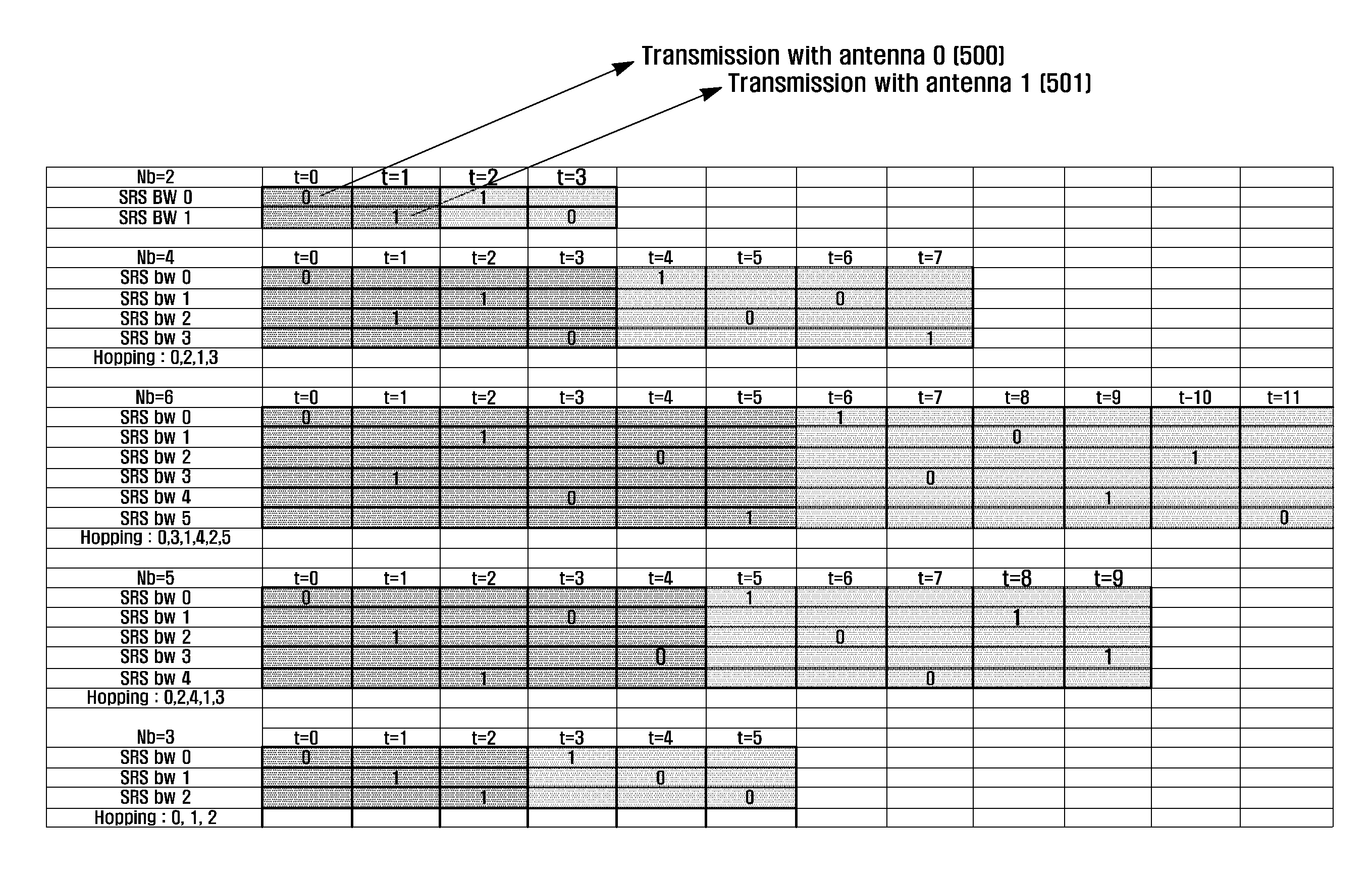
[0046]FIG. 5 illustrates an example of the SRS transmit antenna pattern, and illustrates an SRS transmit antenna index 500, 501 pattern according to the point of time t which transmits SRS in the case where SRS BWs of Nb (Nb={2,3,4,5,6}) exist per one level in the tree structure. At this time, when the number of terminal antennas is M and the number of points intime of the SRS transmission necessary for transmitting SRS to the entire data transmission band by each antenna is K, it becomes K=M*Nb.

[0047]In the drawing, if two antennas are used in turn for the SRS transmission according to the prior art, it can be easily predicted that a specific SRS BW is always transmitted through only one antenna. For example, in the case of Nb=2, when the antenna is used in turns, the SRS BW0 is always transmitted to the antenna 0 and the SRS BW1 is transmitt...

second embodiment

[0070]The second embodiment illustrates an SRS transmit antenna pattern of the present invention, when a terminal has more than two transmit antennas, as in the LTE-Advanced system.

[0071]FIG. 11 illustrates the SRS transmit antenna pattern when the invention is applied to the case where the terminal has three antennas. When the value Nb cannot be divided by 3, which is the number of terminal antenna, antenna 01100, antenna 11101, antenna 21102 are used for the SRS transmission in turns. However, when the value Nb can be divided by 3 which is the number of terminal antenna (Nb=3 of FIG. 11), the terminal groups by combining three SRS transmission points of time corresponding to the number of the SRS transmission band. The SRS is transmitted in the order of antenna 0, antenna 1, and antenna 2 in a first transmission section which is a transmission period for first group (t′=0, 1, 2). In a second transmission section which is a transmission period for the next group (t′=3, 4, 5), an in...


PUM


Abstract

A sounding reference signal transmission method which is efficient in an uplink wireless telecommunications system using a multiple antenna technique and sounding reference signal hopping. A terminal using the multiple antenna technique is equipped with a plurality of antennas, and a base station receives the sounding reference signal transmitted from these antennas and estimates the uplink channel state of each antenna. Moreover, the sounding reference signal performs frequency hopping so that the base station determines the channel condition for the entire bandwidth to which data is transmitted in the uplink system. The sounding reference signal is transmitted through an antenna pattern in which the sounding reference signal can be transmitted through the entire data transmission bandwidth of the uplink system for each antenna of the terminal without additional overhead in this environment.

Description

PRIORITY[0001]This application claims priority under 35 U S. C. §119(a) to Korean patent applications filed in the Korean Intellectual Property Office on Jun. 20, 2008 and Jun. 27, 2008 and assigned Serial Nos. 10-2008-0058581 and 10-2008-0061952, respectively, and the entire disclosure of each of which is hereby incorporated by reference.BACKGROUND OF THE INVENTION[0002]1. Field of the Invention[0003]The present invention relates to an apparatus and method for generating a SRS transmit antenna pattern in an uplink wireless telecommunications system using multiple antennas and Sounding Reference Signal (SRS) hopping.[0004]2. Description of the Related Art[0005]In a wireless telecommunications system, the multiple antenna technique is used as one method for improving uplink performance. As a representative example, the Long Term Evolution (LTE) which is a next generation mobile communication system of the asynchronous cellular mobile communication standard group 3rd Generation Partne...

Claims


Application Information

Patent Timeline
Patent Type & Authority Applications(United States)
IPC IPC(8): H04B1/713H04B7/00H04J13/00
CPCH04B7/0684H04J13/0074H04W72/04H04L5/0051H04L5/0016H04B2201/698H04B1/715H04B1/713H04W72/21H04B7/0897H04L5/0048H04B7/0608
Inventor RO, SANG-MINCHO, JOON-YOUNGLEE, JU-HOLI, YINGYANGHAN, JIN-KYU
Owner SAMSUNG ELECTRONICS CO LTD
Why Eureka
Try Eureka