
Power supply device

Inactive Publication Date: 2009-12-24
TOYOTA JIDOSHA KK
View PDF6 Cites 13 Cited by
  • Summary
  • Abstract
  • Description
  • Claims
  • Application Information

AI Technical Summary

Benefits of technology

[0011]The invention provides a power supply device in which variation in the temperature of a cooling liquid is reduced.
[0021]According to the above-described aspect, the variation in the temperature of the cooling liquid can be reduced in the power supply device. Thus, it is possible to provide the power supply device that is highly stable.

Problems solved by technology

However, the gaseous cooling medium has lower heat conductivity than that of the liquid cooling medium.
However, in the technology described in Japanese Patent No. 2959298, although the cooling liquid is forcibly agitated, only part of the cooling liquid is agitated.
Therefore, each of a plurality of power storage bodies is not sufficiently cooled, and the temperature of the cooling liquid around the power storage bodies varies depending on the portion of the cooling liquid.
As a result, the charging and discharging performance of the entire power supply device is not stable.
Further, the lifetime of the power supply device is decreased.

Method used


Image

  • Power supply device
  • Power supply device
  • Power supply device

Examples


third embodiment

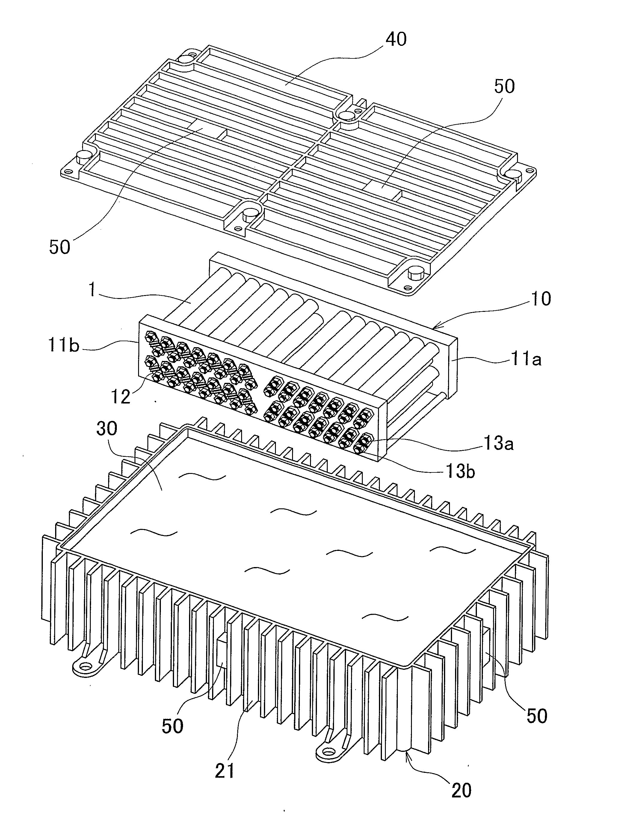
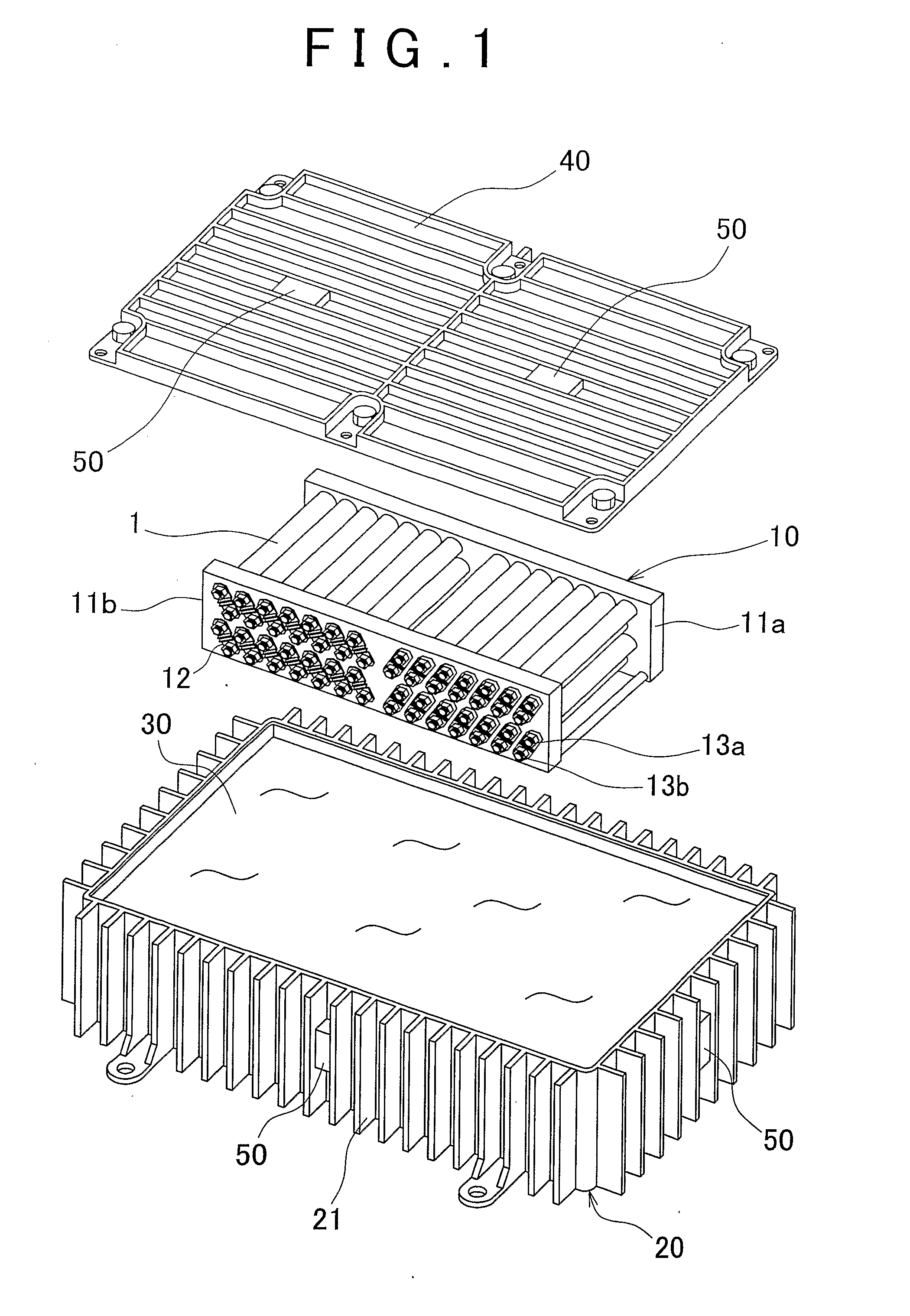
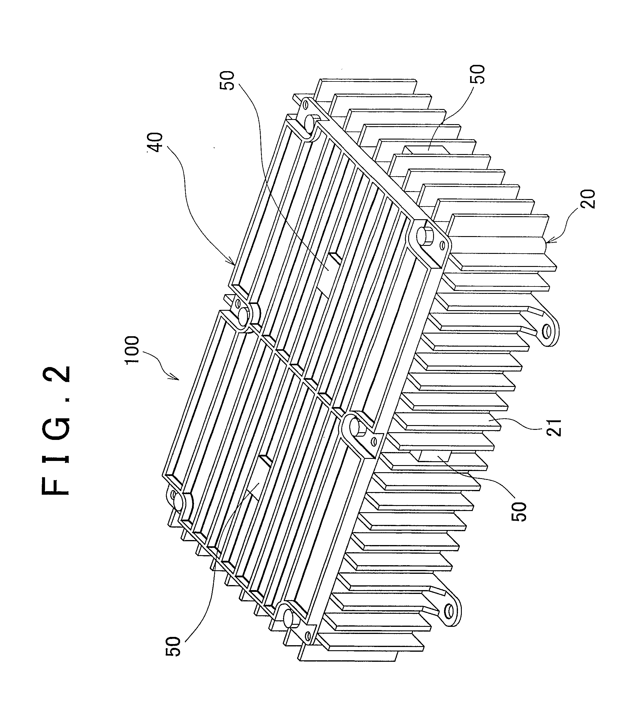
[0044]Particularly, in the third embodiment, each oscillating body 50 is provided with an oscillating plate 51 so that oscillation of the oscillating plate 51 promotes the flow of the cooling liquid. As shown in FIG. 5A, the oscillating plate 51 extends in the direction in which the cooling liquid flows toward the upper portion of the casing 20 due to convection. The oscillating body 50 is provided in one end portion of the oscillating plate 51.

[0045]Accordingly, in the third embodiment, it is possible to promote the flow of the portions of the cooling liquid in the areas among the power storage bodies 1 that constitute the power storage module 10, and to reduce the variation in the temperature distribution of the portion of the cooling liquid around each power storage body 1. Thus, it is possible to equalize the temperature of the cooling liquid in the power storage device 100. Also, by providing each oscillating body 50 with the oscillating plate 51, it is possible to transmit the...

fourth embodiment

[0050]In the fourth embodiment, by disposing the oscillating body 50 directly on the power storage bodies 1, or at a position relatively close to the power storage body 1, it is possible to promote the flow of the portion of the cooling liquid at the position relatively close to the power storage body 1, and to reduce the variation in the temperature distribution of the portion of the cooling liquid around the power storage body 1.

[0051]Thus, in the above-described embodiments, for example, in the case where the plurality of oscillating bodies 50 are disposed in the casing 20 of the power supply device 100, an oscillator, which oscillates in a direction suitable for the flowing direction of the cooling liquid, may be employed as each of the oscillating bodies 50. For example, in FIG. 4A, SAW resonators may be disposed such that a plane of oscillation of the surface acoustic wave from each SAW resonator extends in the flowing direction of the cooling liquid. In this case, the directi...


PUM


Abstract

In a power supply device, a power storage body is disposed in a casing that houses a cooling liquid. The power supply device includes oscillation means that oscillates the cooling liquid.

Description

BACKGROUND OF THE INVENTION[0001]1. Field of the Invention[0002]The invention relates to a power supply device, more specifically, to a cooling control for the power supply device.[0003]2. Description of the Related Art[0004]Power storage bodies, such as battery cells or capacitors, in a power supply device generate heat at the time of charging / discharging. Therefore, by cooling the power storage bodies using a cooling device provided in the power supply device, the temperature of the entire power supply device is controlled to make the output from the power storage bodies constant, to extend the lifetime of the power storage bodies, and to supply constant electric power.[0005]Examples of a method of cooling the power supply device (the power storage bodies) include a gaseous cooling method and a liquid cooling method. In these cooling methods, heat transferred from the power storage bodies to a gaseous or liquid cooling medium is transferred to a casing constituting a part of the p...

Claims


Application Information

Patent Timeline
IPC IPC(8): H01M10/50H01M6/50H01G2/08H01M10/60H01M10/613H01M10/617H01M10/625H01M10/633H01M10/637H01M10/643H01M10/647H01M10/653H01M10/6551H01M10/6567H01M10/6569H01M50/213H01M50/271
CPCH01M2/105H01M2/1077H01M8/04029H01M8/04074H01M8/2475Y02E60/50H01M10/5016H01M10/503H01M10/5046H01M10/5075H05K7/20927H01M10/5004H01M10/625H01M10/6551H01M10/6567H01M10/643H01M10/613Y02E60/10H01M50/213H01M50/271
Inventor MURATA, TAKASHI
Owner TOYOTA JIDOSHA KK
Learn More