Surgical orientation device and method

Active Publication Date: 2009-12-24
ORTHALIGN
View PDF103 Cites 111 Cited by
  • Summary
  • Abstract
  • Description
  • Claims
  • Application Information

AI Technical Summary

Problems solved by technology

A misaligned acetabular prosthetic socket, for example, can lead to complications such as dislocation of the hip joint, decreased joint motion, joint pain, and hastened failure of the implant.
Obtaining satisfactory orientation and positioning of a prosthetic implant is often a chall

Method used


Image

  • Surgical orientation device and method
  • Surgical orientation device and method
  • Surgical orientation device and method

Examples


Embodiment Construction

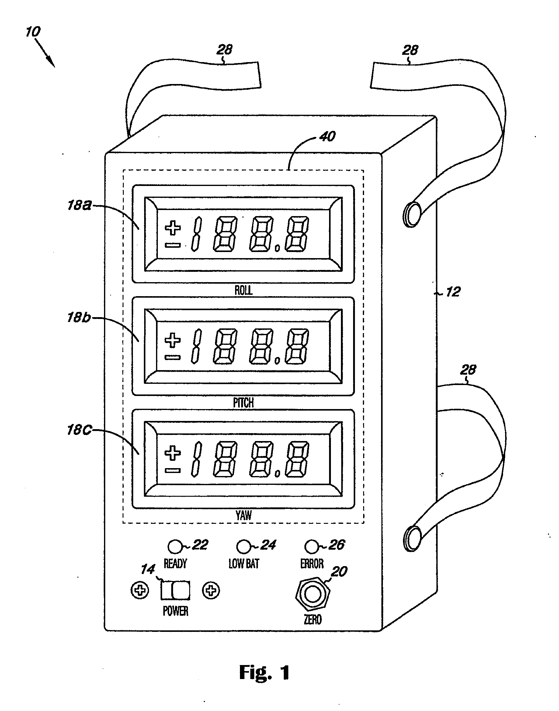
[0036]FIG. 1 is a perspective view of a surgical orientation device 10, according to one embodiment of the present invention. As shown in FIG. 1, the device 10 includes a housing 12, a power switch 14, displays 18, a zero button 20, and indicator lights 22, 24, and 26. The housing 12 contains the electronic circuitry and components necessary for device operation. The housing 12 may be made from any material suitable for use within a surgical field or patient treatment setting. The device 12 may be either disposable or reusable.

[0037]The displays 18, in the embodiment shown in FIG. 1, include a ROLL display 18a, a PITCH display 18b, and a YAW display 18c. These displays 18 provide an indication of the angular orientation of the device in three dimensions, which allow the device to function as a three-dimensional goniometer. The displays 18 may be a gauge of any type (e.g., analog meter, digital display, color bar, and thermocouple meter), and may be integrated on the housing or part ...


PUM


Abstract

A device for detecting and measuring a change in angular position with respect to a reference plane is useful in surgical procedures for orienting various instruments, prosthesis, and implants with respect to anatomical landmarks. One embodiment of the device uses three orthogonal rate sensors, along with integrators and averagers, to determine angular position changes using rate of change information. A display provides position changes from a reference position. Various alignment guides are useful with surgical instruments to obtain a reference plane.

Description

CROSS-REFERENCE TO RELATED APPLICATIONS[0001]This application is a divisional of U.S. patent application Ser. No. 10 / 864,085, filed Jun. 9, 2004, which is hereby incorporated by reference in its entirety, which claims benefit under 35 U.S.C. §119(e) to U.S. provisional application 60 / 476,998 filed Jun. 9, 2003, which is hereby incorporated by reference in its entirety.BACKGROUND OF THE INVENTION[0002]1. Field of the Invention[0003]The present invention relates to medical orientation and positioning devices and in particular to a device for orienting surgical instruments, implements, implants, prosthetics, and anatomical structures.[0004]2. Description of the Related Art[0005]Correct positioning of surgical instruments and implants, used in a surgical procedure, with respect to the patient's anatomy is often an important factor in achieving a successful outcome. In certain orthopaedic implant procedures, such as totals hip replacement (THR) or arthroplasty, total knee arthroplasty (T...

Claims


Application Information

Patent Timeline
IPC IPC(8): A61B17/58A61B5/103A61B17/17A61B19/00A61F2/02A61F2/34A61F2/46
CPCA61B5/1071A61F2002/4687A61B17/175A61B19/5244A61B2017/00115A61B2019/5248A61B2019/5251A61F2/34A61F2/4609A61F2/4657A61F2002/30538A61F2002/4632A61F2002/4668A61F2250/0006A61B2017/1778A61B5/4504A61B2034/2048A61B34/20A61B2034/2051A61B17/1778
Inventor STONE, A. CURTRUSSIAL, JOSEPH F.
Owner ORTHALIGN
Why Eureka
Try Eureka