In-liquid-substance detection sensor

a detection sensor and liquid substance technology, applied in the field can solve the problems of limited size reduction, reduced reliability of in-liquid substance detection sensors, and difficulty in providing channels with high accuracy, so as to achieve the effect of easy improvement of detection accuracy and size reduction

Active Publication Date: 2009-12-31
MURATA MFG CO LTD
View PDF10 Cites 10 Cited by
  • Summary
  • Abstract
  • Description
  • Claims
  • Application Information

AI Technical Summary

Benefits of technology

[0008]In light of the above, preferred embodiments of the present invention provide an in-liquid-substan

Problems solved by technology

In the in-liquid-substance detection sensor configured as described above, since the SAW device chips are mounted on the top surface of the base substrate by flip-chip mounting, size reduction is limited.
Moreover, if the resin layer that seals the bump electrodes, provided for mounting the SAW device chips, absorbs the liquid or is melted by being in contact with the liquid, and thus the bump electr

Method used


Image

  • In-liquid-substance detection sensor
  • In-liquid-substance detection sensor
  • In-liquid-substance detection sensor

Examples


first preferred embodiment

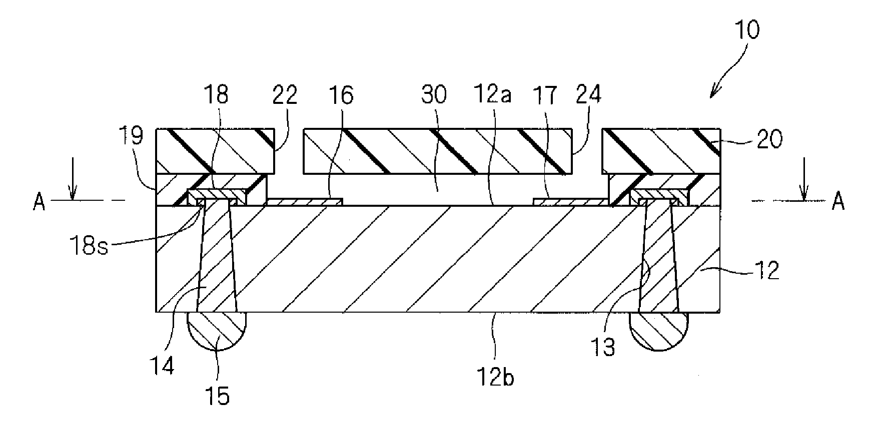
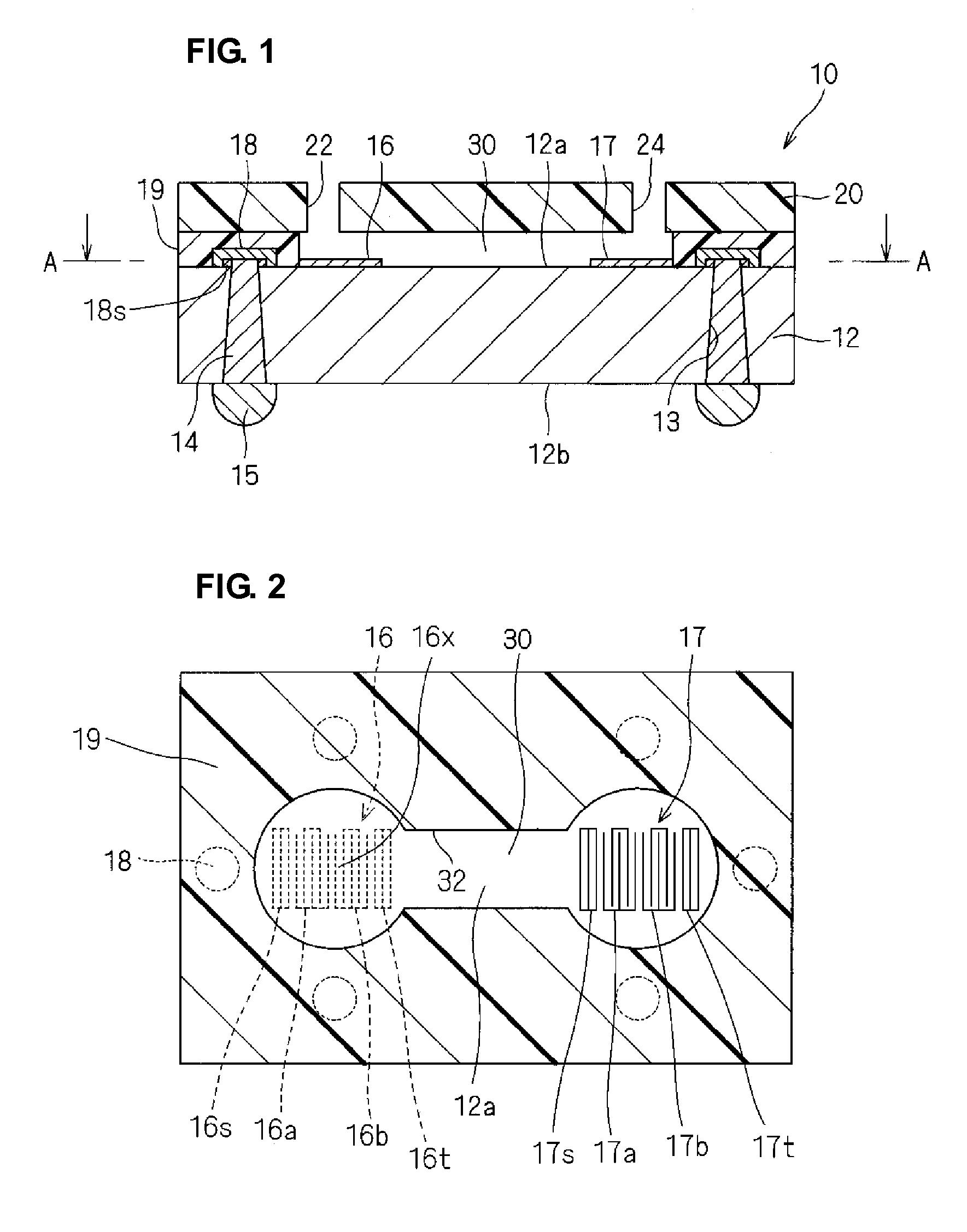
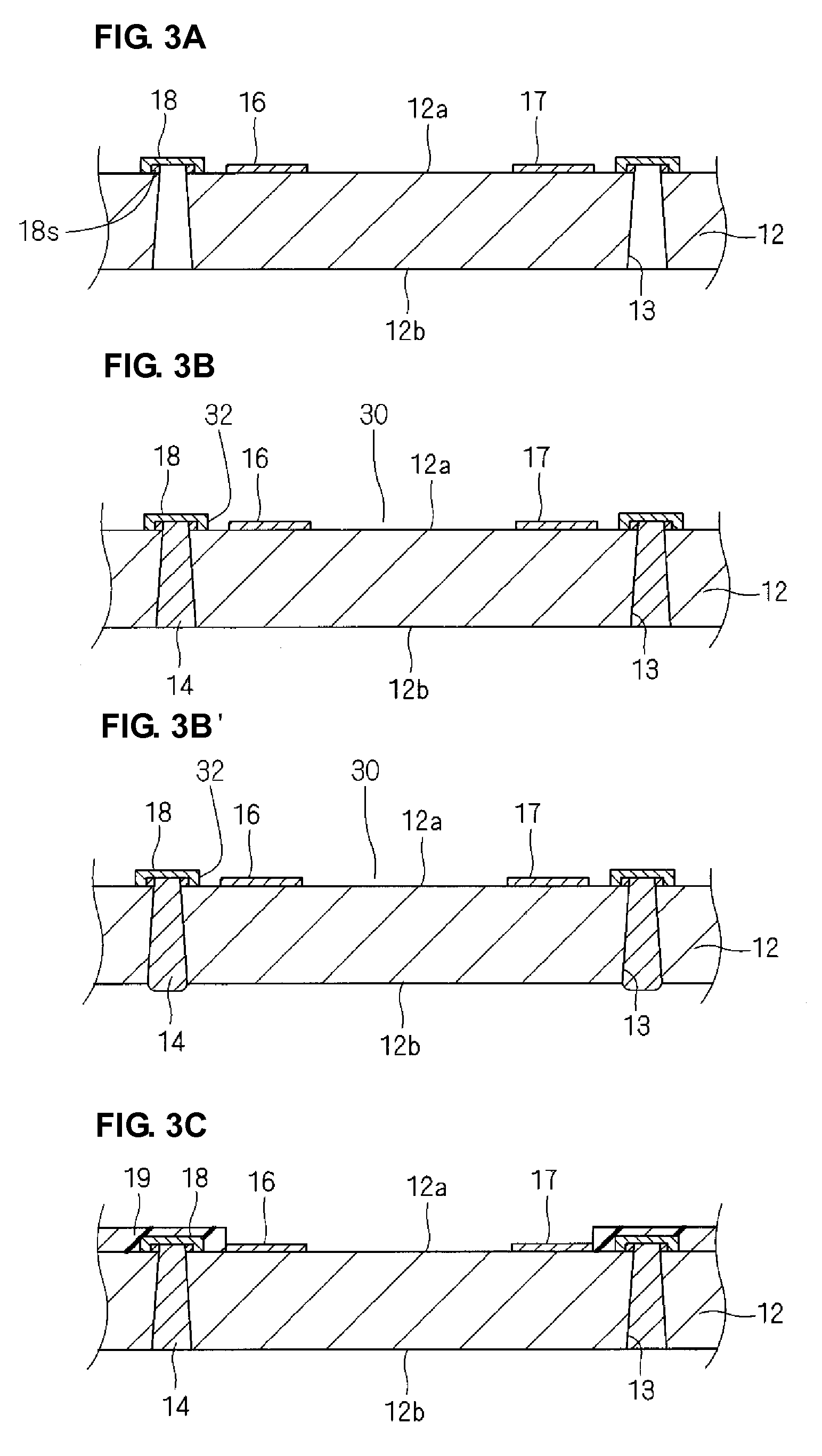
[0039]An in-liquid-substance detection sensor 10 according to a first preferred embodiment will be described with reference to FIGS. 1 to 4G.

[0040]As shown in FIGS. 1 and 2 as a cross-sectional view and a sectional view taken along the line A-A in FIG. 1, respectively, the in-liquid-substance detection sensor 10 includes a piezoelectric substrate 12 and a lid member 20 bonded together with a support layer 19 interposed therebetween. The piezoelectric substrate 12 is provided on a back surface 12b thereof, remote from the lid member 20, with solder bumps 15 functioning as outer electrodes. For example, the piezoelectric substrate 12 is composed of LiTaO3, the lid member 20 is made of resin film, and the support layer 19 is made of adhesive resin.

[0041]The piezoelectric substrate 12 is provided on a top surface 12a thereof, facing the lid member 20, with a conduction pattern of metal film formed by deposition or other suitable process. The conduction pattern includes two SAW devices 1...

second preferred embodiment

[0067]An in-liquid-substance detection sensor according to the second preferred embodiment will now be described with reference to FIGS. 5 to 7G.

[0068]An in-liquid-substance detection sensor 10x of the second preferred embodiment has substantially the same configuration as the in-liquid-substance detection sensor of the first preferred embodiment. Hereinafter, differences between the two will be mainly described, and like reference numerals will denote like elements.

[0069]As shown in FIG. 5 as a cross-sectional view, the in-liquid-substance detection sensor 10x includes, substantially the same as in the first preferred embodiment, a piezoelectric substrate 12 and a lid member 20x bonded together, with a support layer 19 interposed therebetween. The piezoelectric substrate 12 has two SAW devices 16 and 17 on a top surface 12a thereof.

[0070]Unlike in the first preferred embodiment, the lid member 20x is a piezoelectric substrate composed of, for example, LiTaO3. The lid member 20x has...


PUM


Abstract

An in-liquid-substance detection sensor that achieves size reduction and detection accuracy improvement includes a piezoelectric substrate, at least two SAW devices provided on one major surface of the piezoelectric substrate and each having at least one IDT electrode defining a sensing portion, outer electrodes provided on the other major surface of the piezoelectric substrate and electrically connected to the SAW devices through vias extending through the piezoelectric substrate, a channel-defining member provided on the one major surface of the piezoelectric substrate so as to surround the SAW devices and a region connecting the SAW devices to each other, thereby defining sidewalls of a channel, and a protective member bonded to the one major surface of the piezoelectric substrate with the channel-defining member interposed therebetween, thereby sealing the channel, the protective member having at least two through holes communicating with the channel.

Description

BACKGROUND OF THE INVENTION[0001]1. Field of the Invention[0002]The present invention relates to in-liquid-substance detection sensors, and in particular, to an in-liquid-substance detection sensor including a surface acoustic wave (SAW) device.[0003]2. Description of the Related Art[0004]Some in-liquid-substance detection sensors, which detect substances contained in liquids, include SAW devices.[0005]For example, an in-liquid-substance detection sensor 131, shown in FIGS. 8 and 9 as a perspective view and an exploded perspective view, respectively, includes a base substrate 132 and protective members 134 and 136 bonded to both surfaces of the base substrate 132 with adhesion layers 133 and 135 interposed therebetween. SAW device chips 137 and 138 having sensing portions are mounted on the top surface of the base substrate 132 by flip-chip bonding. As shown in FIG. 10 as a cross-sectional view, this mounting is performed such that bump electrodes 116a and 116b are sealed by a resin...

Claims


Application Information

Patent Timeline
IPC IPC(8): G01N29/02
CPCG01N29/022G01N2291/0423G01N2291/022G01N29/222
Inventor YAMADA, HAJIMEAIZAWA, NAOKOKOSHIDO, YOSHIHIROFUJIMOTO, KOJIYABE, TORUKADOTA, MICHIO
Owner MURATA MFG CO LTD
Why Eureka
Try Eureka