LNG fuel supply system

a fuel supply system and liquefied natural gas technology, applied in the direction of machines/engines, container filling under pressure, discharging methods, etc., can solve the problems of fuel not being reliably supplied, vaporized gas can be excessively generated, and it is difficult to charge and store lng than lpg, so as to achieve efficient charging of the different storage tanks and reliable supply of different storage tanks

Inactive Publication Date: 2009-12-31
HYUNDAI MOTOR CO LTD
View PDF12 Cites 20 Cited by
  • Summary
  • Abstract
  • Description
  • Claims
  • Application Information

AI Technical Summary

Benefits of technology

[0010]Various aspects of the present invention are directed to provide a fuel supply system, and in particular an LNG fuel supply system, having advantages of securely and reliably supplying different storage tanks of a vehicle with LNG fuel and efficiently charging the different storage tanks with LNG fuel.

Problems solved by technology

Particularly, the liquefaction temperature of liquid propane gas (LPG) is about minus 47° C., however, the liquefaction temperature of LNG is about minus 160° C. such that it is more difficult to charge and store the LNG than the LPG.
Moreover, vaporized gas can be excessively generated inside the storage tank in this process.
Further, there is a problem with conventional systems in that the fuel is not reliably supplied by a difference of vaporization pressure when at least two storage tanks are used in the case in which remaining fuel amounts are different.
Particularly, it is not appropriate or effective when a large output is required.

Method used


Image

  • LNG fuel supply system
  • LNG fuel supply system
  • LNG fuel supply system

Examples


Embodiment Construction

[0023]Reference will now be made in detail to various embodiments of the present invention(s), examples of which are illustrated in the accompanying drawings and described below. While the invention(s) will be described in conjunction with exemplary embodiments, it will be understood that present description is not intended to limit the invention(s) to those exemplary embodiments. On the contrary, the invention(s) is / are intended to cover not only the exemplary embodiments, but also various alternatives, modifications, equivalents and other embodiments, which may be included within the spirit and scope of the invention as defined by the appended claims.

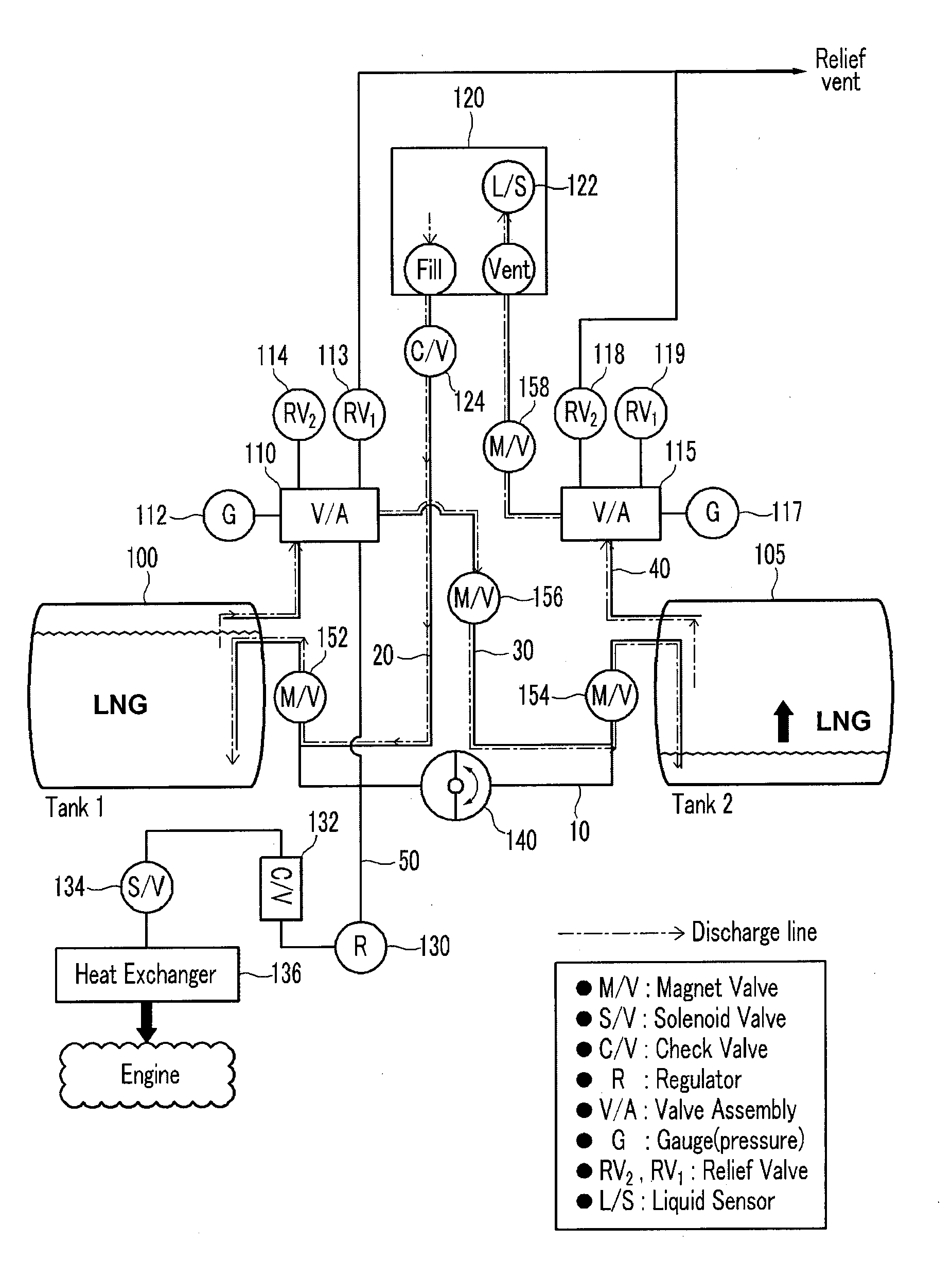
[0024]FIG. 1 is a schematic diagram showing a state in which LNG is being charged in a LNG fuel supply system according to the present invention.

[0025]Referring to FIG. 1, an LNG fuel supply system includes a first LNG tank 100, a second LNG tank 105, a connecting line 10, a charging line 20, a direct line 30, a vent line 40, and a su...


PUM


Abstract

An LNG supply system may include first and second LNG tanks, a connecting line connecting the first LNG tank with the second LNG tank and in which a time relay valve is disposed, a charging line one side of which is connected to a fuel supply portion and the other side of which is connected to the first LNG tank for charging fuel, a vent line, one side of which is connected to the second LNG tank and the other side of which is open, a direct line connecting the first LNG tank and the second LNG tank, and a supply line branched from one side of the connecting line to supply an engine with LNG, wherein the time relay valve is opened for a predetermined period so as to equalize the amount of LNG that is charged in the first LNG tank and the second LNG tank.

Description

CROSS-REFERENCE TO RELATED APPLICATION[0001]The present application claims priority to Korean Patent Application No. 10-2008-0061054, filed on Jun. 26, 2008, the entire contents of which are incorporated herein for all purposes by this reference.BACKGROUND OF THE INVENTION[0002]1. Field of the Invention[0003]The present invention relates to an engine of a vehicle, and more particularly to a liquefied natural gas (LNG) fuel supply system for securely supplying an engine with LNG and efficiently charging two different fuel tanks with LNG.[0004]2. Description of Related Art[0005]When charging a storage tank, the temperature of the storage tank is lowered by vaporization of the LNG to store the LNG in a liquid state.[0006]Particularly, the liquefaction temperature of liquid propane gas (LPG) is about minus 47° C., however, the liquefaction temperature of LNG is about minus 160° C. such that it is more difficult to charge and store the LNG than the LPG.[0007]The time for the temperature ...

Claims


Application Information

Patent Timeline
Patent Type & Authority Applications(United States)
IPC IPC(8): F17C5/02F02M21/02
CPCB60K15/03006F17C2270/0168Y02T10/32F02M21/0215F02M21/0224F02M21/0239F02M21/0245F02M21/0287F02D19/023F02D19/027F17C2201/0114F17C2205/0332F17C2205/0335F17C2205/0338F17C2221/033F17C2223/0161F17C2223/033F17C2225/0161F17C2225/033F17C2227/0107F17C2227/0302F17C2227/0388F17C2250/032F17C2250/043F17C2250/0447F17C2265/032F17C2265/066F17C7/02Y02T10/30F02M21/02F02M37/00
Inventor KWON, SUNGGU
Owner HYUNDAI MOTOR CO LTD
Why Eureka
Try Eureka