Electromechanical element and electronic equipment using the same
a technology of electromechanical switch and electronic equipment, applied in the direction of piezoelectric/electrostrictive device details, device details, protective devices, etc., can solve the problems of difficult to satisfy such requests, high response speed, and use of electromechanical switch in radio communication, and achieve high precision and response characteristic high
- Summary
- Abstract
- Description
- Claims
- Application Information
AI Technical Summary
Benefits of technology
Problems solved by technology
Method used
Image


Examples
embodiment 1
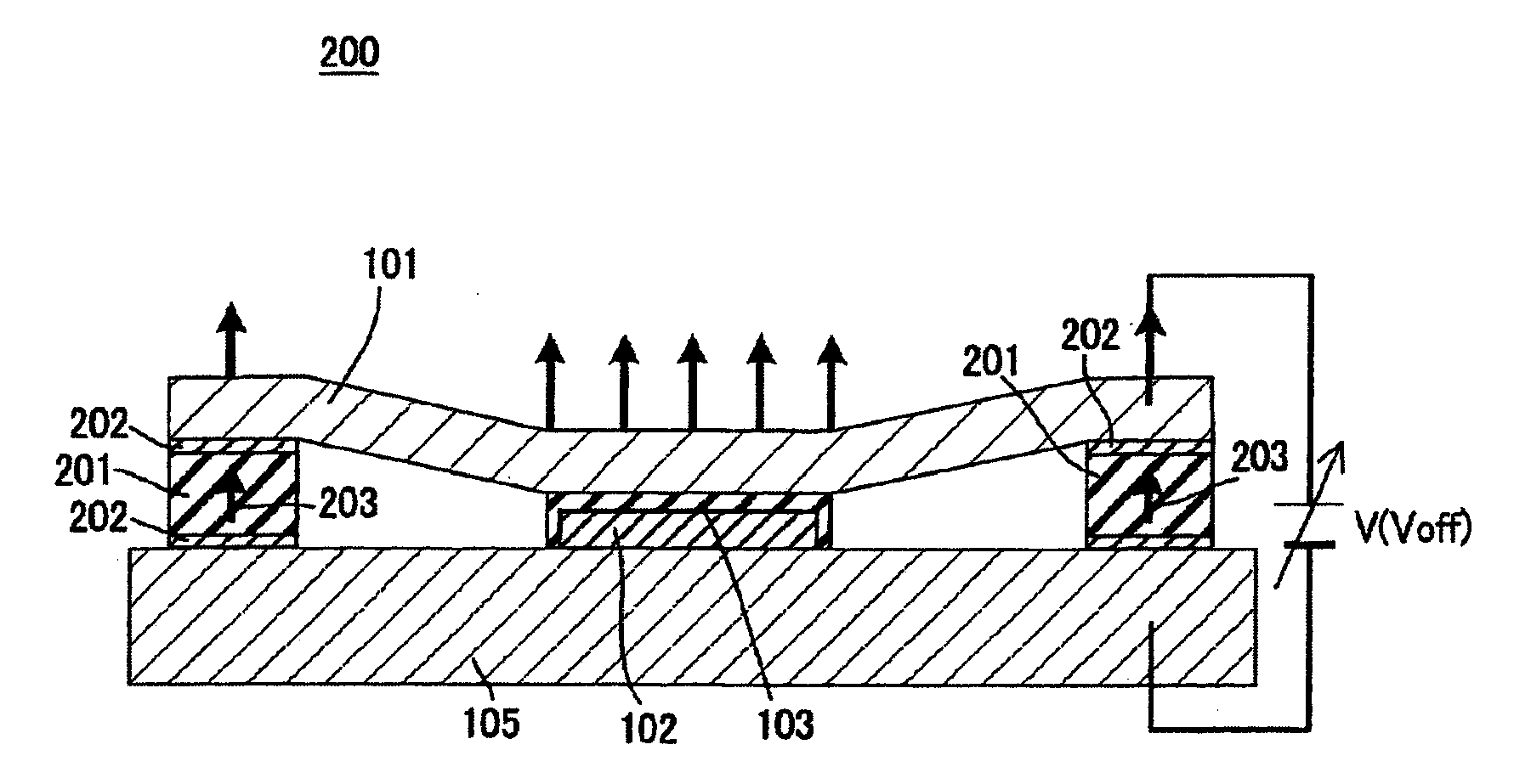
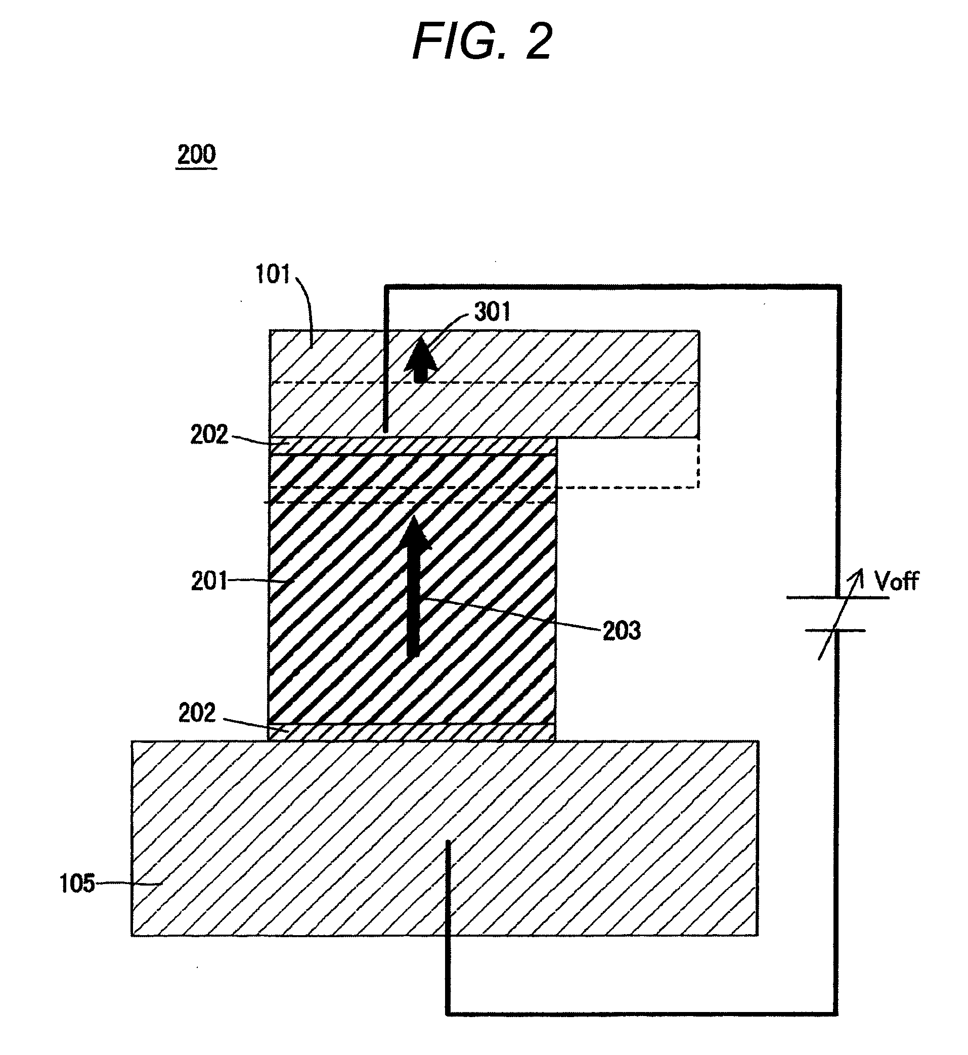
[0113]An electromechanical switch in Embodiment 1 of the present invention is characterized in that, as shown in FIGS. 1A and 1B, a piezoelectric body is provided to posts as supporting bodies of the electromechanical switch respectively, a movable electrode as a second electrode is displaced in the direction perpendicular to a substrate by a normal strain of the piezoelectric body, and a force for releasing the movable electrode from a fixed electrode as a first electrode (releasing force) can be adjusted by increasing a spring force of the movable electrode.
[0114]FIGS. 1A and 1B are sectional views showing a configuration of an electromechanical switch in Embodiment 1 of the present invention, wherein FIG. 1A is a sectional view showing a transition state from ON to OFF, and FIG. 1B is a sectional view showing an OFF state. An electromechanical switch 200 illustrated in the present embodiment employs a piezoelectric body 201 as the posts of the electromechanical switch 100 shown i...
embodiment 2
[0123]The present embodiment is characterized in that the piezoelectric body is formed in the posts of the electromechanical switch, and the movable electrode is displaced with respect to the substrate in the horizontal direction by a shearing strain of the piezoelectric body to increase a spring force of the movable electrode.
[0124]FIGS. 3A and 3B are sectional views showing a configuration of an electromechanical switch in Embodiment 2 of the present invention, wherein FIG. 3A is a sectional view showing a transition state from ON to OFF, and FIG. 3B is a sectional view showing an OFF state. An electromechanical switch 300 shown in the present embodiment has the similar configuration to the electromechanical switch 200 shown in FIG. 2, but is different in that the piezoelectric body 201 generates a large shearing strain.
[0125]FIG. 4 is a sectional view showing a post of the electromechanical switch in Embodiment 2 of the present invention in an enlarged fashion. In a situation tha...
embodiment 3
[0128]The present embodiment is characterized in that the piezoelectric body and an elastic body are formed in the posts of the electromechanical switch, and the movable electrode is displaced with respect to the substrate in the vertical / horizontal directions by the shearing strain of the piezoelectric body to increase a spring force of the movable electrode.
[0129]FIGS. 5A and 5B are sectional views showing a configuration of an electromechanical switch in Embodiment 3 of the present invention, wherein FIG. 5A is a sectional view showing a transition state from ON to OFF, and FIG. 5B is a sectional view showing an OFF state. An electromechanical switch 400 illustrated in the present embodiment is different in that an elastic body 211 is provided to side surfaces of the piezoelectric bodies 201 respectively, in addition to the configuration of the electromechanical switch 300 shown in FIG. 3.
[0130]FIG. 6 is a sectional view showing a post of the electromechanical switch in Embodimen...
PUM
 Abstract
Description
Claims
Application Information
 - R&D
- Intellectual Property
- Life Sciences
- Materials
- Tech Scout
- Unparalleled Data Quality
- Higher Quality Content
- 60% Fewer Hallucinations
Browse by: Latest US Patents, China's latest patents, Technical Efficacy Thesaurus, Application Domain, Technology Topic, Popular Technical Reports.
© 2025 PatSnap. All rights reserved.Legal|Privacy policy|Modern Slavery Act Transparency Statement|Sitemap|About US| Contact US: help@patsnap.com