Eureka AIR delivers breakthrough ideas for toughest innovation challenges, trusted by R&D personnel around the world.

Co-axial basket mill and method of use

Inactive Publication Date: 2009-12-31
DERRICO EDWARD
View PDF5 Cites 7 Cited by
  • Summary
  • Abstract
  • Description
  • Claims
  • Application Information

AI Technical Summary

Benefits of technology

[0014]It is an object of the invention to provide basket mill in which the flow of slurry through the basket is precisely controlled.
[0015]It is a further object of the invention to provide a basket mill that does not require extensive maintenance.
[0016]It is another object of the invention to provide a basket mill wherein the process vessel may be used as a simple disperser.
[0017]It is yet another object of the invention to provide a basket mill in which grinding of particles may be accomplished with reduced energy consumption.
[0022]1. There is no stabilizer bushing in contact with the grinding media, thus greatly decreasing required maintenance.
[0023]2. Furthermore, with the new design, the machine can be operated as a simple disperser by spinning only the impeller shaft without starting the main grinding media agitator shaft. This is useful since it eliminates a prior step in the process where the slurry must first be mixed in a separate disperser machine.

Problems solved by technology

The first type of machine, described above with respect to FIG. 1, is generally preferred due to the presence of the center-mounted impeller 32, but has numerous maintenance problems.
With the separate propellers of the second design, the propeller is separate, so there is no need for the bottom mounted bushing of the first design which is under constant attack by the action of the grinding media However, the offset nature of the propeller does not provide the better flow, and control over the flow of material as in the first design.

Method used


Image

  • Co-axial basket mill and method of use
  • Co-axial basket mill and method of use
  • Co-axial basket mill and method of use

Examples


Embodiment Construction

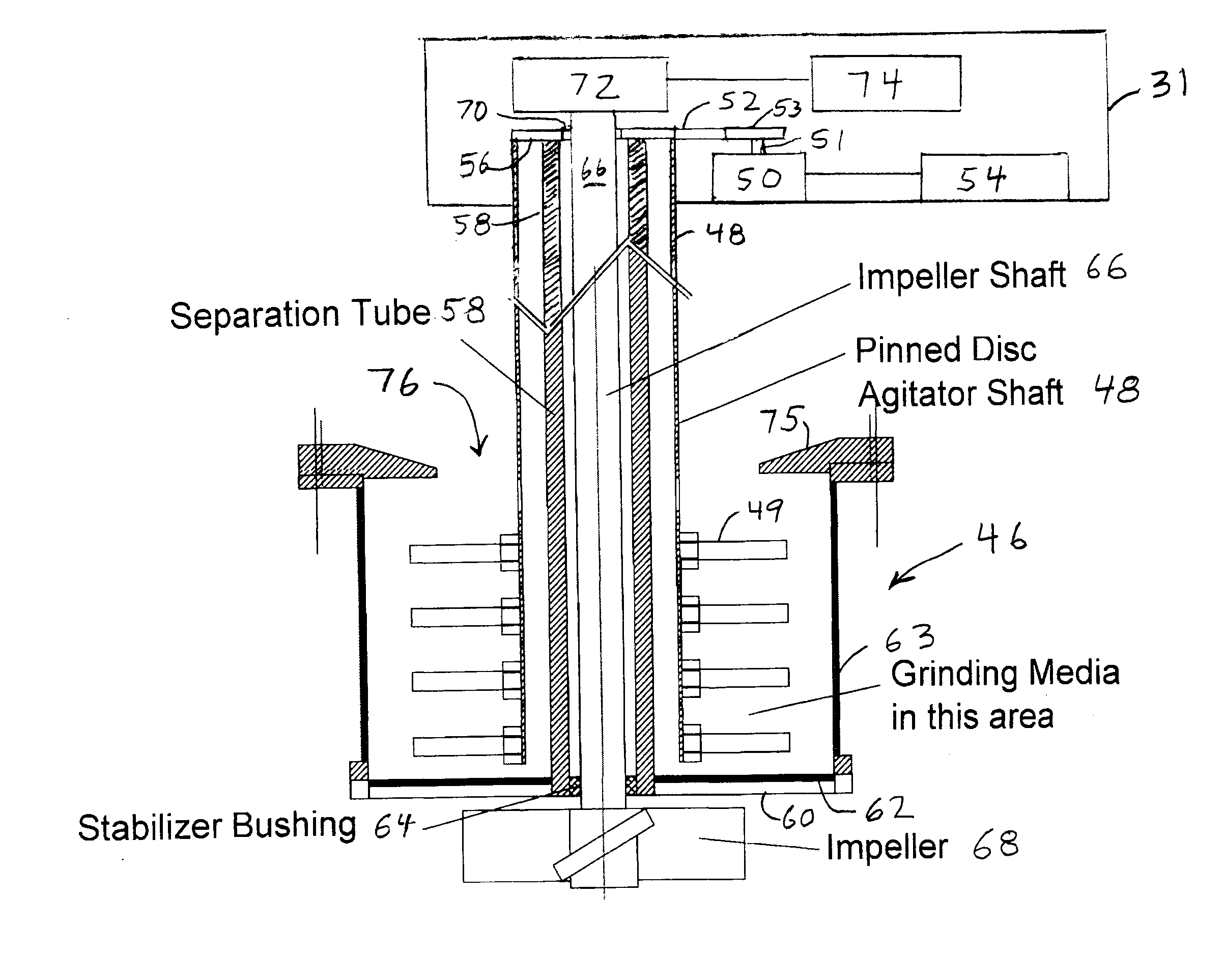
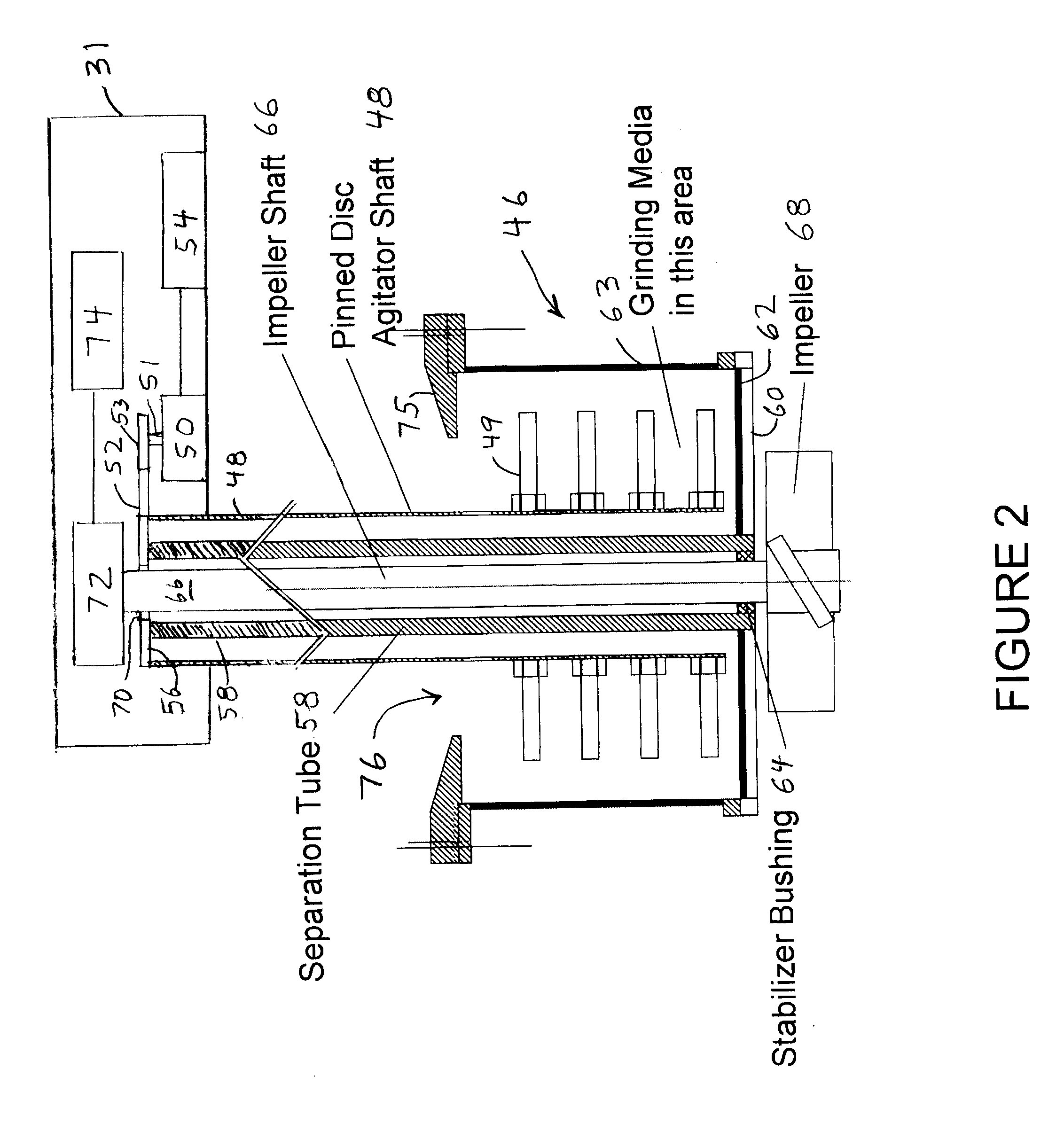
[0027]Referring to FIG. 2, there is shown a cross-sectional view of a basket 46 and related apparatus incorporating features of the present invention. Although the present invention will be described with reference to the single embodiment shown in the drawing, it should be understood that the present invention can be embodied in many alternate forms of embodiments. In addition, any suitable size, shape or type of elements or materials could be used.

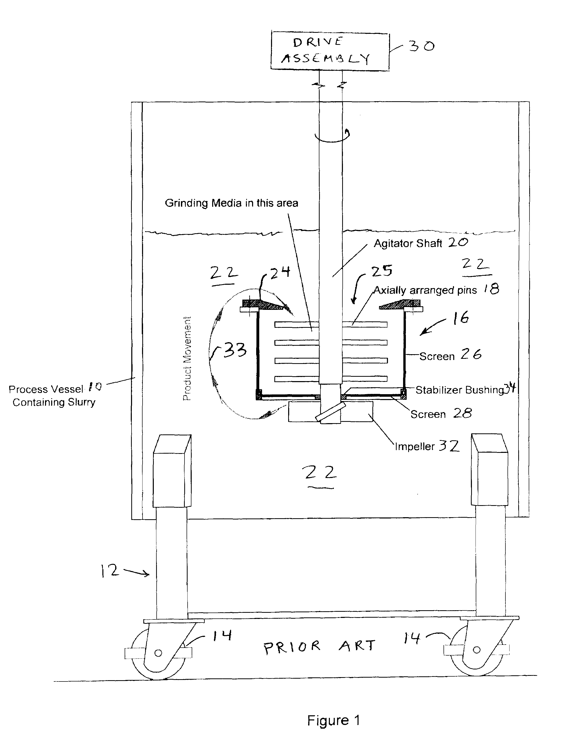
[0028]Basket 46 may be utilized for grinding slurry 22 in a process vessel 10, as in FIG. 1. However, the structure is different than that of FIG. 1, as described below. A tubular agitator shaft 48, having pinned discs 49 extending radially therefrom to agitate the mixture in the basket 46, is rotated by a first electrical motor 50, within a drive assembly 31. Motor 50 has a shaft 51 and a pulley or gear 53 mounted for rotation with shaft 51. Pulley or gear 53 may be connected to shaft 48 by a belt or chain 52, respectively. An electrica...


PUM


Abstract

For use in a basket mill having a process vessel in which particles are ground so as to reduce their size, a basket for retaining a grinding medium, having an opening in its top and a screen at its bottom. A first shaft extends into the basket and has a grinding assembly extending from the shaft. A first drive apparatus rotates the first shaft at a first rotational rate. A second shaft is coaxial with the first shaft and has an impeller for causing material to be ground to move into the basket through the opening and out of said basket through the screen. A second drive apparatus rotates the second shaft at a second rotational rate independent of the first rotational rate. The first shaft may be a tube. A tube may be disposed within the first shaft, and have at its end a bushing for receiving for rotation the second shaft. The bushing may be located outside of a region of the basket where grinding media is disposed. Methods for operating the apparatus.

Description

[0001]This application claims priority under 35 U.S.C. §119(e) from provisional patent application Ser. No. 61 / 076,627 filed on Jun. 28, 2008, the entire content of which is incorporated herein by reference.BACKGROUND OF THE INVENTION[0002]1. Field of the Invention[0003]The present invention relates to apparatus and methods for grinding materials into fine particles. More particularly, it relates to those apparatus methods in which a basket mill is used.[0004]2. Background Art[0005]A basket mill is a machine used to reduce the particle size of slurries. Typical uses are for the manufacture of paint or ink where pigment particles must be reduced to microscopically small sizes.[0006]Such mills can accommodate a wide range of volume depending on the volume and viscosity of the slurry to be processed. Typical volumes range from 0.5 liter for a table-top mill to as much as 40 liters for a full manufacturing mill.[0007]Referring to FIG. 1, such machines typically have a process vessel 10 ...

Claims


Application Information

Patent Timeline
IPC IPC(8): B02C17/16B02C23/36
CPCB02C17/24B02C17/168
Inventor D'ERRICO, EDWARD
Owner DERRICO EDWARD
Why Eureka
Eureka Blog
Learn More