Injector for injection moulding of plastic materials

Inactive Publication Date: 2009-12-31
INGLASS SRL
View PDF3 Cites 0 Cited by
  • Summary
  • Abstract
  • Description
  • Claims
  • Application Information

AI Technical Summary

Benefits of technology

[0013]Thanks to this arrangement, the injector according to the invention renders possible the application of the vacuum within the mould in an efficient way, without requiring any particular machining operations on the mould itself, thus ensuring an excellent quality of the items obtained following upon injection of the plastic material in the mould.
[0014]The use of the injector according to the invention is particularly—albeit not exclusively—advantage

Problems solved by technology

However, with the above methodology the injection of the second material within the first material previously injected can at times generate burns, such as the one designated by 45 in FIG. 5a, deriving from the combustion of air imprisoned in the cavity of the mould and subjected to the extremely high moulding pressures.
These burns are visible in the case of transparent articles, such as precisely the lenses of lights for motor vehicles, and involve the

Method used


Image

  • Injector for injection moulding of plastic materials
  • Injector for injection moulding of plastic materials
  • Injector for injection moulding of plastic materials

Examples


Embodiment Construction

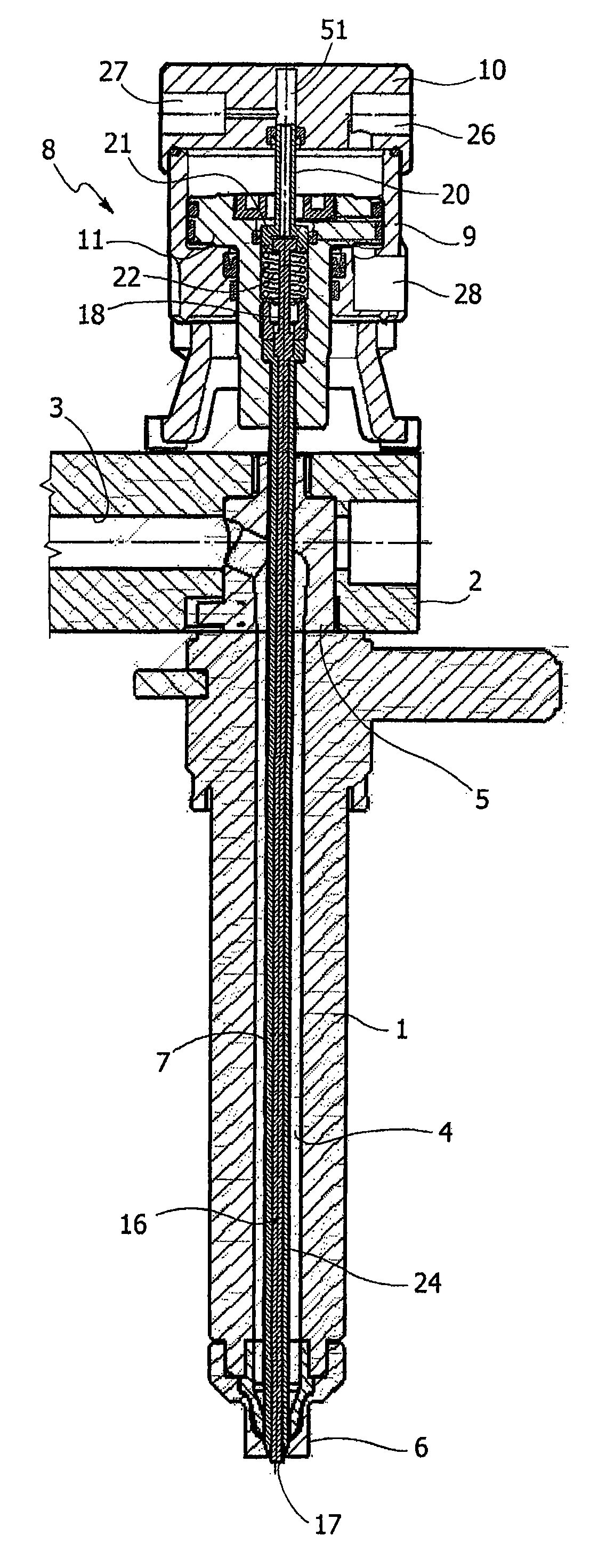
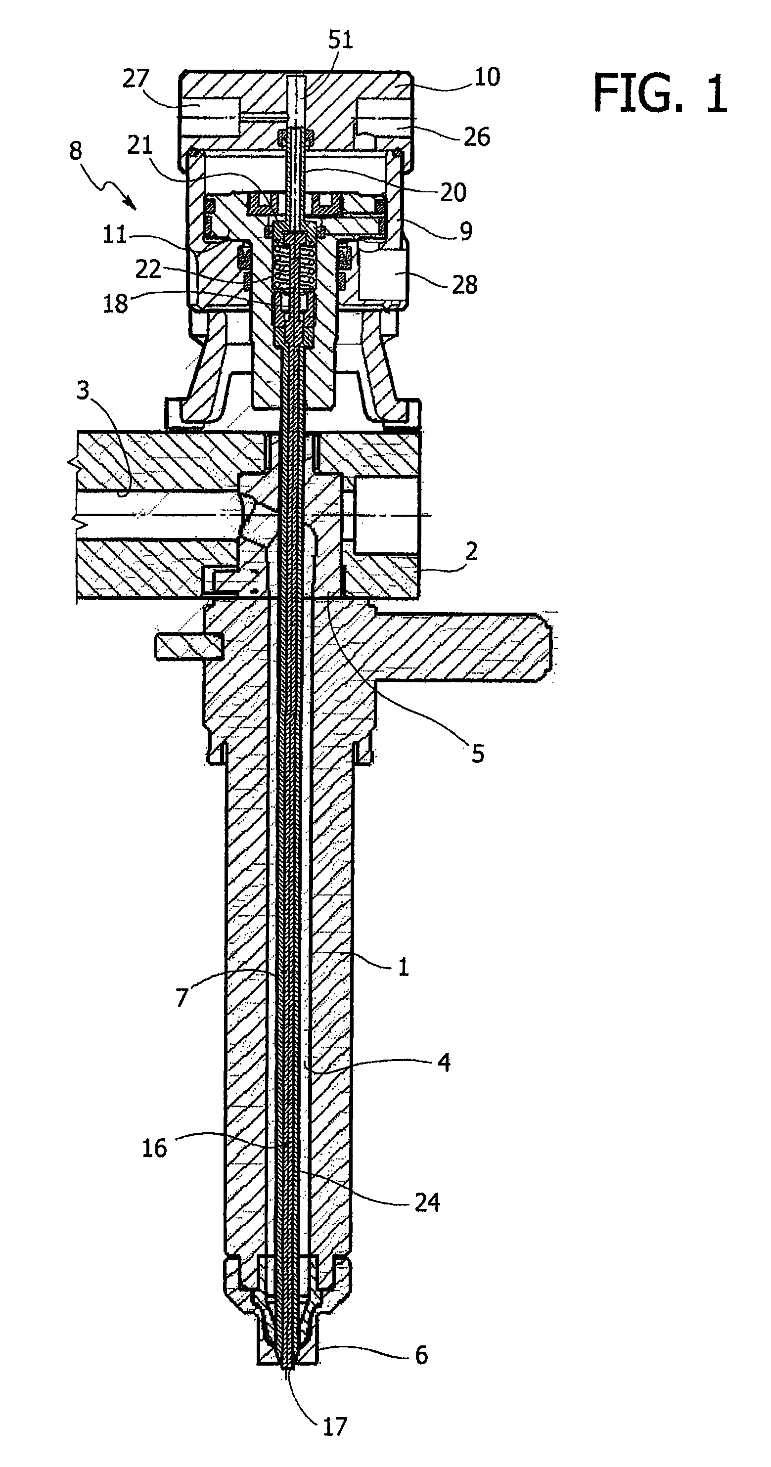
[0021]With reference initially to FIG. 1, an injector for injection moulding of plastic materials according to the invention basically comprises a tubular body 1, applied, in the case of the example illustrated, underneath a hot-chamber arm 2, equipped with a feed pipe 3 for supply of the fluid plastic material to be injected. The pipe 3 communicates with the cavity 4 of the tubular body 1 through a bushing 5, shaped so as to direct the flow of plastic material towards a terminal 6 of the injector, through which the plastic material is injected into the mould. In the case of the example illustrated, the terminal 6 comprises, in a way in itself known (for example, from the U.S. Pat. No. 6,832,909) a tip and a ring nut.

[0022]The passage through the terminal 6 is controlled in a conventional way by means of an axial plug 7, which is mobile along the cavity 4 of the body 1 and can be displaced, in the way clarified in what follows, between an advanced position of closing of the passage ...


PUM

PropertyMeasurementUnit
Pressureaaaaaaaaaa
Vacuumaaaaaaaaaa

Abstract

An injector for injection moulding of plastic materials incorporates a vacuum device for creating a suction pressure within the mould in an area corresponding to the injection point, prior to the injection of the plastic material.

Description

BACKGROUND OF THE INVENTION[0001]The present invention relates in general to the moulding of plastic materials, and regards more in particular an injector for moulds for injection moulding of plastic materials.STATE OF THE PRIOR ART[0002]Traditionally, injectors of this sort comprise a body having an axial passage for introduction of the fluid plastic material within a mould; a plug, which is axially mobile in the body for controlling said passage; and actuator means for governing the displacement of the plug between an advanced position for closing, and a retracted position for opening said passage, in which an injection point is provided.[0003]An injector of this type is described and illustrated, for example, in the European patent No. EP-B-1277560.[0004]In particular applications of multimaterial or multicolour moulding, typically in the moulding in a number of steps of transparent lenses or shields for the lights of motor vehicles within one and the same mould, there frequently...

Claims


Application Information

Patent Timeline
IPC IPC(8): B29C45/28B29C45/34
CPCB29C45/2806B29C2045/2893B29C2045/2862B29C45/34
Inventor DAL BO, PETERSCALON, LORENZO
Owner INGLASS SRL
Why Eureka
Try Eureka