Image processing apparatus and image processing method
- Summary
- Abstract
- Description
- Claims
- Application Information
AI Technical Summary
Benefits of technology
Problems solved by technology
Method used
Image
Examples
embodiments
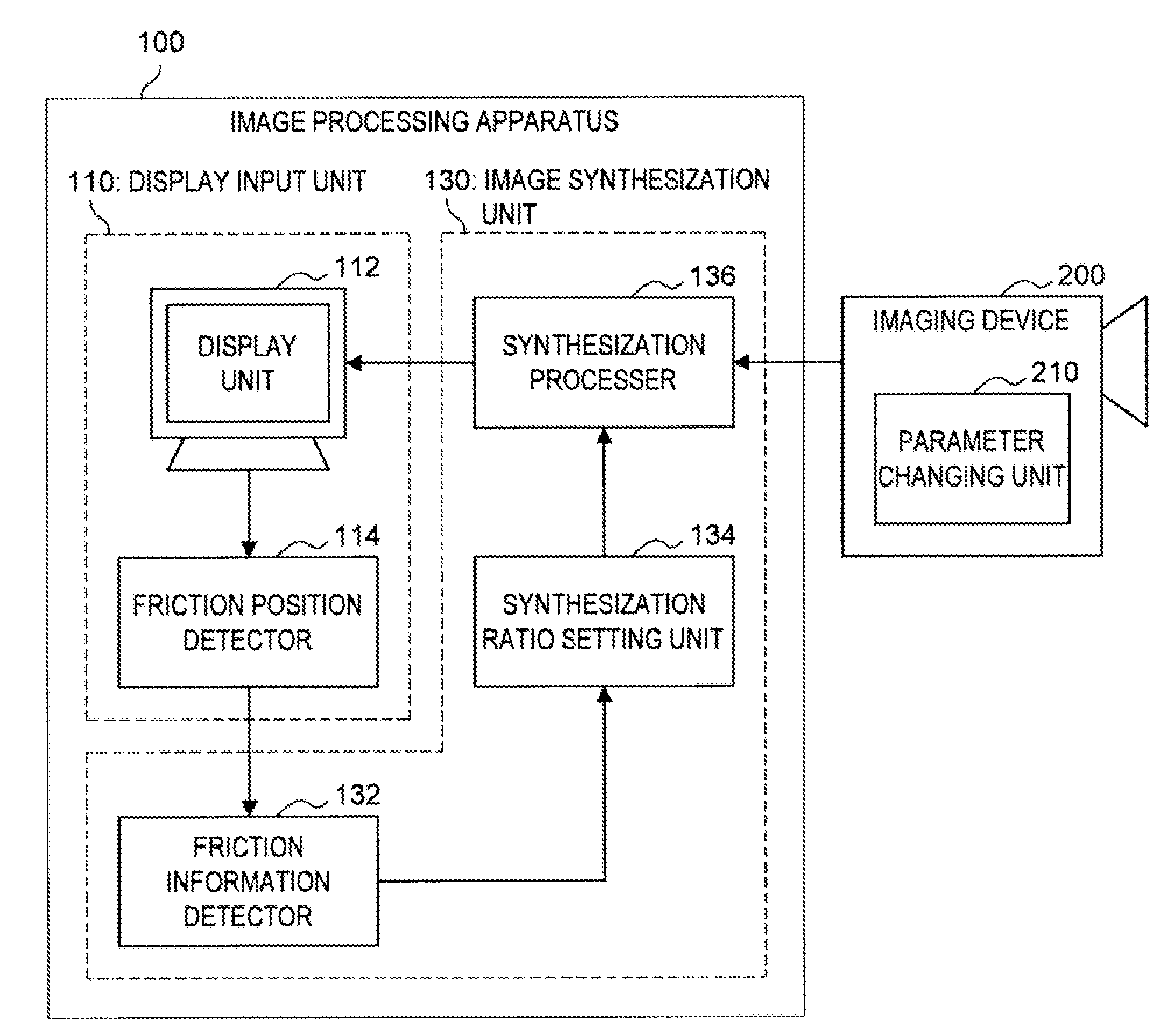
[0045]Hereinafter, one embodiment of the present invention will be described. The embodiment relates to a technique for synthesizing a plurality of continuously taken images. However, the technique is also applied to a plurality of continuously taken images while changing predetermined parameters thereof. In addition, the present embodiment relates to a technique in which a user rubs a screen on which an image is displayed, and accordingly, continuously taken other images are synthesization-processed in response to the rubbing motion thereof. Therefore, the technique relates to a user's operation system.
[Principle Explanation]
[0046]First, the principle of a method of the present embodiment will be described with reference to FIG. 3. FIG. 3 is a principle explanation view for explaining the principle of a technique according to the present embodiment.
[0047]A touch panel and a plurality of continuously taken images are schematically shown in FIG. 3. These images represent images which...
application example 1
Firework Imaging
[0093]Next, one example application of the present embodiment will be described with reference to FIGS. 12A to 12C. FIGS. 12A to 12C are explanation views showing examples when the technique according to the present embodiment is applied to a stage of firework imaging. The stage of firework imaging shown in the present case is an example of a case where an object image intended by a photographer appeared in a time difference. As described above, the image processing apparatus 100 according to the present embodiment is also preferably used for a stage where it is not possible to control a state of the object.
[0094]FIGS. 12A to 12C are those typically showing continuously taken images intended for moments at which two fireworks are exploded. Incidentally, these series of images are those imaging a state where a firework on the left side exploded first, and a few minutes later, a firework on the right side exploded thereafter.
[0095]First, FIG. 12A will be referred to. A...
application example 2
Scenery Imaging
[0098]Next, one example application of the present embodiment will be described with reference to FIG. 13. FIG. 13 is an explanation view showing an example of a case where the technique according to the present embodiment is applied to a stage of scenery imaging. The stage of the scenery imaging shown in this case is an example of a case where objects are present on the front and the back, and therefore, to focusing on the front and the back at the same time is not possible. As described above, the image processing apparatus 100 according to the present embodiment is also preferably used for a stage where imaging is difficult by any means.
[0099]An image P(t1) and an image P(t2) are depicted in FIG. 13. The image P(t1) is an image taken so as to be focused on the back. On the other hand, the image P(t2) is an image taken so as to be focused on the front. In the case where scenery is taken, when focusing on a back building, mountain, or the like, the front leaves or th...
PUM
 Abstract
Description
Claims
Application Information
 - R&D
- Intellectual Property
- Life Sciences
- Materials
- Tech Scout
- Unparalleled Data Quality
- Higher Quality Content
- 60% Fewer Hallucinations
Browse by: Latest US Patents, China's latest patents, Technical Efficacy Thesaurus, Application Domain, Technology Topic, Popular Technical Reports.
© 2025 PatSnap. All rights reserved.Legal|Privacy policy|Modern Slavery Act Transparency Statement|Sitemap|About US| Contact US: help@patsnap.com


