
Liquid crystal panel and liquid crystal display apparatus

a liquid crystal display and liquid crystal panel technology, applied in the direction of instruments, polarising elements, optical elements, etc., can solve the problems of black display level at the circumference of the panel falling, easy generation of liquid crystal panel light leakage, etc., to prevent light leakage from the circumference of the panel and good image display

Active Publication Date: 2009-12-31
NITTO DENKO CORP
View PDF4 Cites 22 Cited by
  • Summary
  • Abstract
  • Description
  • Claims
  • Application Information

AI Technical Summary

Benefits of technology

The present invention provides a liquid crystal panel and display apparatus that can prevent light leakage from the circumference of the panel, even when the optical film used in the panel contracts or stretches due to changes in heat or humidity. This is achieved by using a first and second pressure-sensitive adhesive layer with different creep values, which allows for a more stable and secure attachment of the optical film to the liquid crystal cell. The invention also includes a bezel to further enhance the image display in the panel.

Problems solved by technology

As a result, light leakage is easily generated from the liquid crystal panel.
The light leakage causes, for example, a problem that a black display level at a circumference of the panel falls when the liquid crystal panel is in a black display state.

Method used


Image

  • Liquid crystal panel and liquid crystal display apparatus
  • Liquid crystal panel and liquid crystal display apparatus
  • Liquid crystal panel and liquid crystal display apparatus

Examples


example 1

[0176]The pressure-sensitive adhesive (5) was coated (a dry thickness of 20 μm) onto a surface of the protective film of the polarizing plate (1), and then the resultant was adhered onto a viewing side surface of a liquid crystal cell (trade name: AQUOS, manufactured by Sharp Corp.) in a VA mode for a 37-inch screen (461 mm in vertical and 819 mm in lateral). Separately, the pressure-sensitive adhesive (2) was coated (a dry thickness of 20 μm) onto a surface of the optical compensation layer of the polarizing plate (2), and then the resultant was adhered onto the surface reverse to the viewing side surface of the above liquid crystal cell to produce a liquid crystal panel. However, the polarizing plate (1) was adhered to make the absorption axis direction of its polarizer parallel to long side of the liquid crystal cell. The polarizing plate (2) was adhered to make the absorption axis direction of its polarizer parallel to short side of the liquid crystal cell.

example 2

[0177]A liquid crystal panel was produced in the same way as in Example 1 except that the pressure-sensitive adhesive (7) was used for the adhesion of the polarizing plate (1), and the pressure-sensitive adhesive (2) was used for the adhesion of the polarizing plate (2).

example 3

[0178]A liquid crystal panel was produced in the same way as in Example 1 except that the pressure-sensitive adhesive (8) was used for the adhesion of the polarizing plate (1), and the pressure-sensitive adhesive (3) was used for the adhesion of the polarizing plate (2).


PUM

PropertyMeasurementUnit
thicknessaaaaaaaaaa
tensile shearing forceaaaaaaaaaa
thicknessaaaaaaaaaa

Abstract

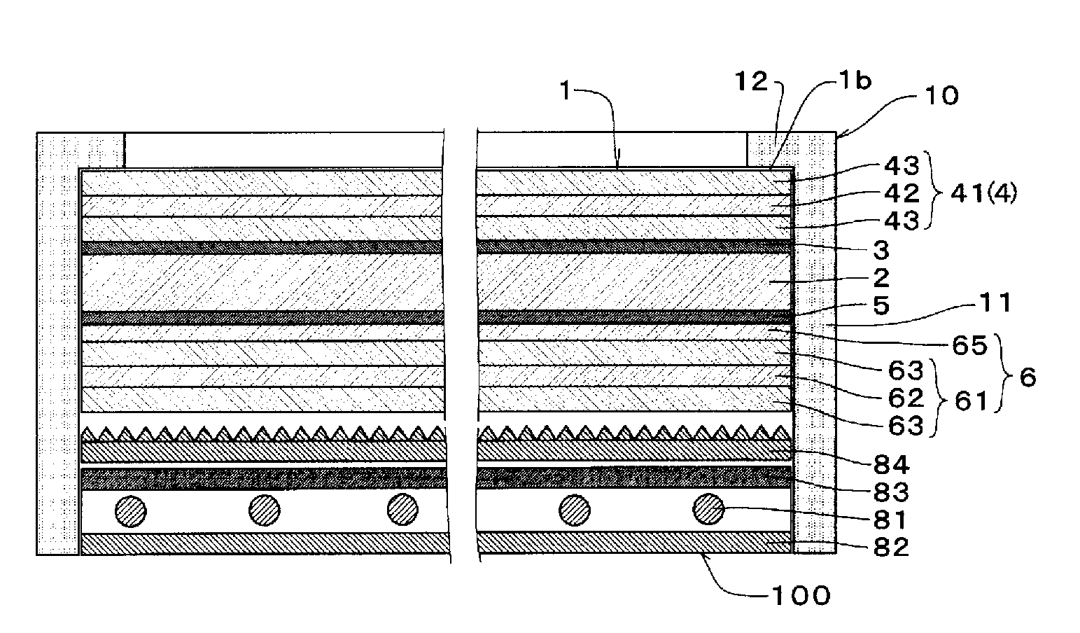
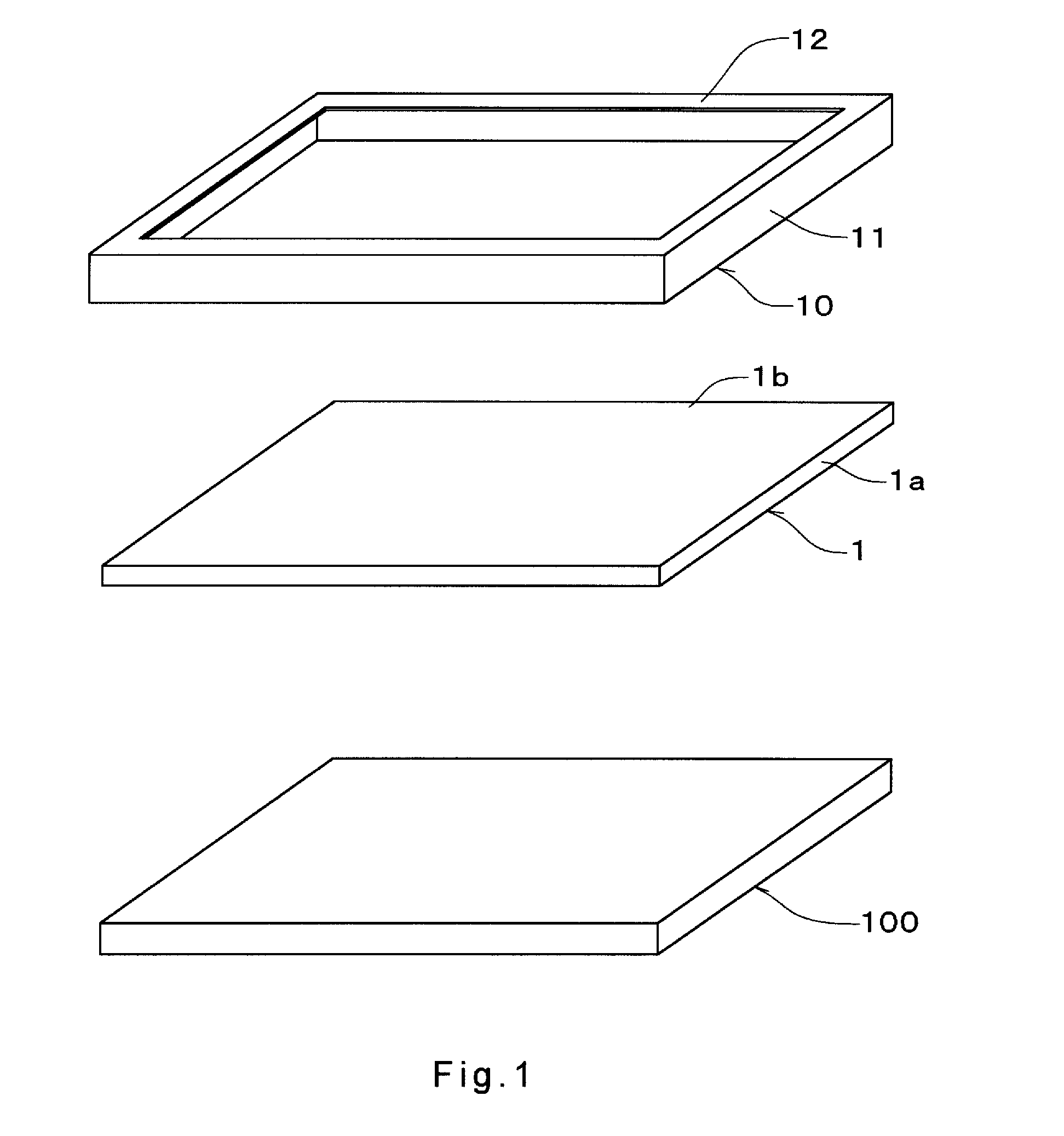
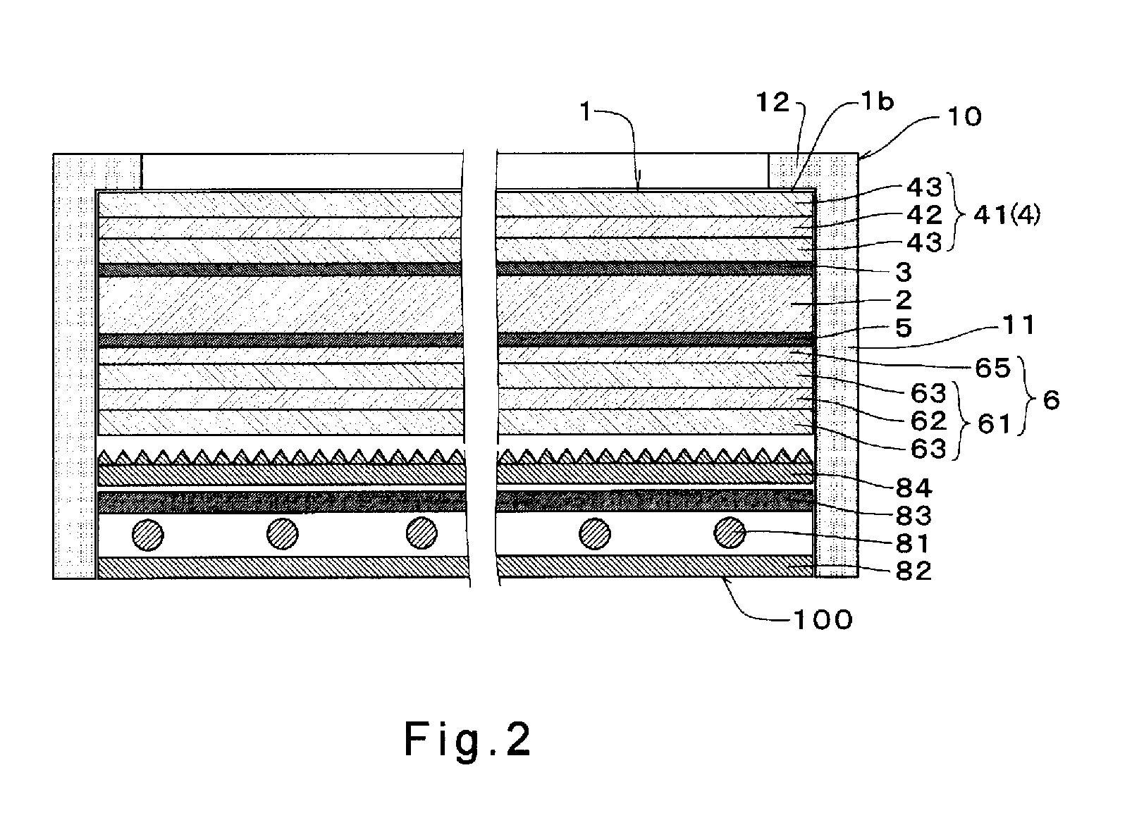
A liquid crystal panel has a first optical film (4) adhered to a viewing side of a liquid crystal cell (2) through a first pressure-sensitive adhesive layer (3), and a second optical film (6) adhered to the reverse side of the liquid crystal cell (2) through a second pressure-sensitive adhesive layer (5). A creep value (L1) of the first pressure-sensitive adhesive layer (3) is from 50 to 3000 μm. A creep value (L2) of the second pressure-sensitive adhesive layer (5) is from 10 to 400 μm. The creep value (L1) of the first pressure-sensitive adhesive layer (3) is larger than the creep value (L2) of the second pressure-sensitive adhesive layer (5). The creep value means the shift amount after one hour of the pressure-sensitive adhesive layer having a thickness of 20 μm in a case where a tensile shearing force of 4.9 N is applied to an adhesive area of 10 mm2 at 23° C.

Description

TECHNICAL FIELD[0001]The present invention relates to a liquid crystal panel, and a liquid crystal display apparatus.BACKGROUND ART[0002]Conventionally, a liquid crystal panel of a liquid crystal display apparatus is generally provided with a liquid crystal cell, and polarizing plates arranged on both surface sides of the liquid crystal cell, respectively. The liquid crystal cell has two liquid crystal cell substrates, a spacer interposed between the two substrates, and a liquid crystal material injected into a gap between the two substrates. The liquid crystal cell, into which the liquid crystal material is injected, itself has birefringence to generate a retardation. In order to compensate for this retardation of the liquid crystal cell, an optical compensation layer is usually provided between the liquid crystal cell and the polarizing plate (for example, Patent Document 1).[0003]Usually, these optical films, such as polarizing plates are each adhered to a liquid crystal cell thr...

Claims


Application Information

Patent Timeline
Patent Type & Authority Applications(United States)
IPC IPC(8): G02F1/1335G02F1/1333
CPCC08L2312/00C09J133/02G02F2202/28G02B5/3033G02F1/133528C09J133/066G02F1/1335C09J133/00G02B5/30
Inventor SATAKE, MASAYUKITOYAMA, YUUSUKEKINJOU, NAOTAKASHIMIZU, TAKASHIYOSHIDA, KENTAROU
Owner NITTO DENKO CORP
Learn More