
Liquid crystal optical modulator and the process for producing the same

a technology of optical modulator and liquid crystal, applied in non-linear optics, instruments, optics, etc., can solve the problems of narrow seal width, deformation, and deformation of liquid crystal characteristics, and achieve the effect of reducing the amount of external wiring, reducing the seal width, and increasing reliability

Inactive Publication Date: 2009-12-31
CITIZEN WATCH CO LTD
View PDF0 Cites 6 Cited by
  • Summary
  • Abstract
  • Description
  • Claims
  • Application Information

AI Technical Summary

Benefits of technology

[0016]Furthermore, by using a metal seal, it is possible to prevent the permeation of moisture that causes deterioration of the liquid crystal layer and the seal width can be reduced by comparison with that of a resin seal.
[0060]With the liquid crystal optical modulator in accordance with the present invention, by dripping a liquid crystal under vacuum, a configuration can be obtained in which no injection port is required, permeation of moisture via the injection port can be prevented, and reliability can be increased.

Problems solved by technology

In the above-described configuration in which a liquid crystal is held between the substrates with a resin, a problem is associated with the degradation of liquid crystal characteristics caused by permeation of moisture into the liquid crystal layer through the resin.
Another problem is that a spacer is required to set the predetermined distance between the substrates, and yet another known problem is that deformations occur due to physical properties of the resin and a narrow seal width is difficult to realize.
Furthermore, a low-melting metal has to be sandwiched between the thin films of high-melting metals on the surfaces of both substrates and, therefore, the production process is complex.

Method used


Image

  • Liquid crystal optical modulator and the process for producing the same
  • Liquid crystal optical modulator and the process for producing the same
  • Liquid crystal optical modulator and the process for producing the same

Examples


Embodiment Construction

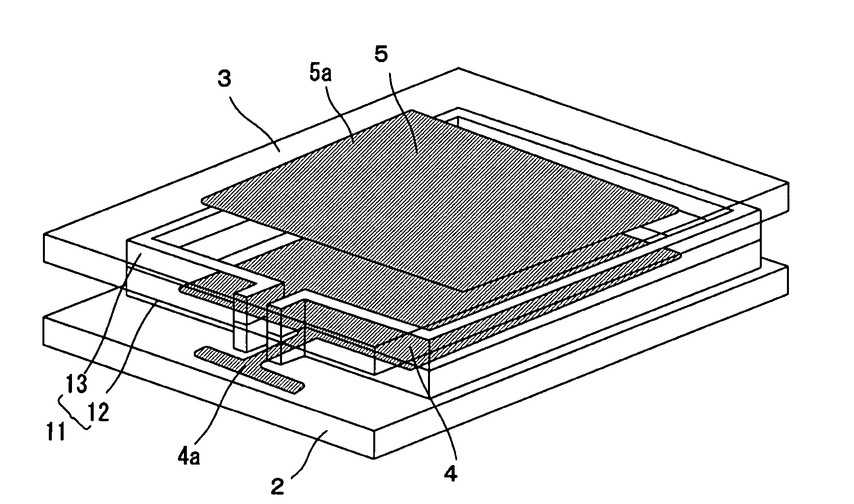
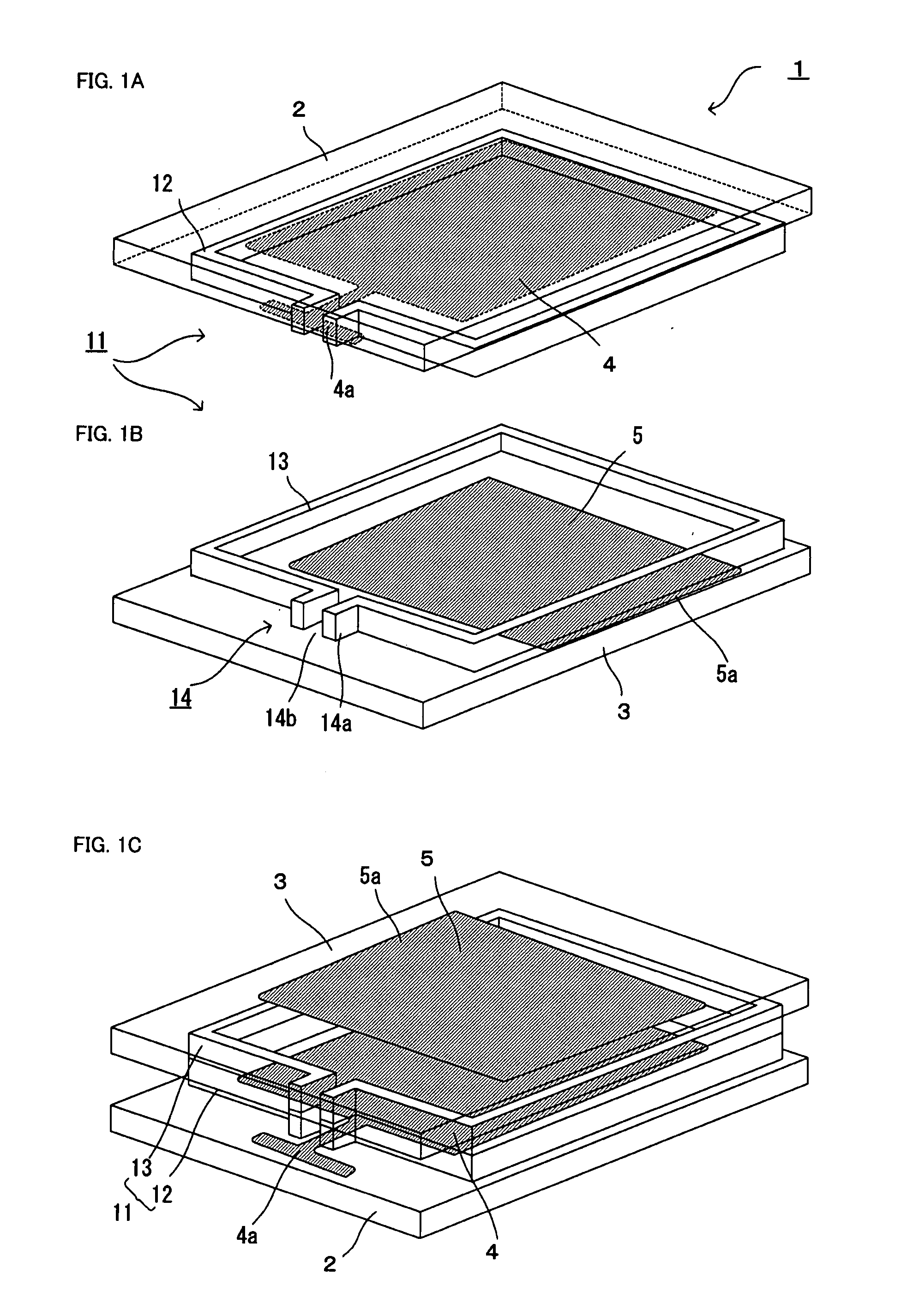
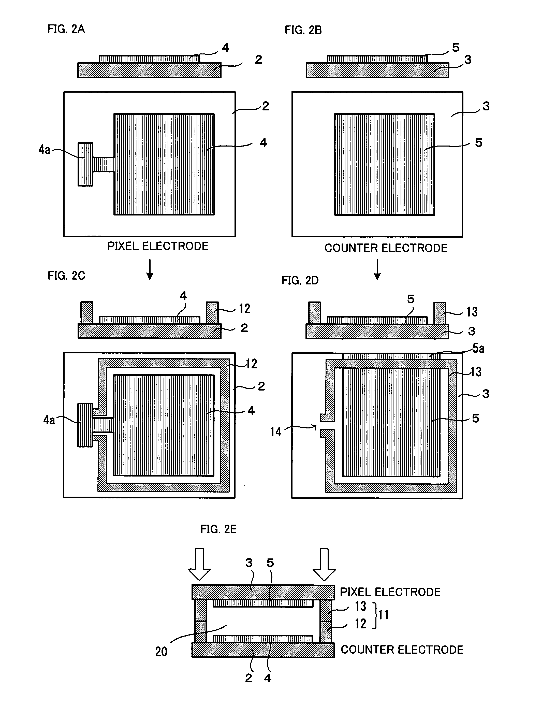
[0083]The liquid crystal optical modulator in accordance with the present invention will be described below in greater detail with reference to the appended drawings. First to fifth configuration examples of the liquid crystal optical modulator in accordance with the present invention will be described below.

[0084]FIGS. 1, 2 are a schematic perspective view, a cross-sectional view, and a plan view for explaining the first configuration example of the liquid crystal optical modulator in accordance with the present invention. FIGS. 6 to 8 are a schematic perspective view, a cross-sectional view, and a plan view for explaining the second configuration example of the liquid crystal optical modulator in accordance with the present invention. FIGS. 9, 10 are a schematic perspective view, a cross-sectional view, and a plan view for explaining the third configuration example of the liquid crystal optical modulator in accordance with the present invention. FIGS. 11 to 14 are a schematic pers...


PUM

PropertyMeasurementUnit
distanceaaaaaaaaaa
circumferenceaaaaaaaaaa
transparent electrically conductiveaaaaaaaaaa

Abstract

A space between substrates in a liquid crystal optical modulator can be sealed with a metal by using a simple configuration. In a seal structure between the substrates constituting a liquid crystal cell in a liquid crystal optical modulator, metal members are provided on the opposing surfaces of the two substrates, and the base metal surfaces of the metal members are brought into direct contract and joined. As a result, a low-melting metal such as a solder that has been conventionally introduced into the joint section becomes unnecessary, and a metal seal providing for strong bonding can be formed with a simple configuration. The liquid crystal optical modulator has a first substrate having a first electrode pattern including a pixel electrode, a second substrate having a second electrode pattern including a counter electrode, and a metal seal disposed so as to be sandwiched between the first substrate and the second substrate. The metal seal is formed between a first metal member composed of a metal material and formed on the first substrate and a second metal member composed of a metal material and formed on the second substrate by directly joining the metal surfaces of the two metal members.

Description

BACKGROUND OF THE INVENTION[0001]1. Field of the Invention[0002]The present invention relates to a liquid crystal optical modulator such as a liquid crystal display or liquid crystal optical switch and to a process of producing the same, and more particularly to a seal for sealing the liquid crystal.[0003]2. Description of the Related Art[0004]A liquid crystal optical modulator such as a liquid crystal display or liquid crystal optical switch is formed, for example, by providing a liquid crystal layer between substrates comprising electrodes.[0005]Usually, a liquid crystal cell is formed by bonding substrates disposed with a certain gap therebetween with a resin, injecting a liquid crystal through an injection port into the space bounded by the resin and the substrates, and sealing after the injection of the liquid crystal has been completed. In the above-described configuration in which a liquid crystal is held between the substrates with a resin, a problem is associated with the d...

Claims


Application Information

Patent Timeline
Patent Type & Authority Applications(United States)
IPC IPC(8): G02F1/1339G02F1/1343G02F1/13
CPCG02F1/1339
Inventor IDE, MASAFUMI
Owner CITIZEN WATCH CO LTD
Learn More