LED illumination device

Inactive Publication Date: 2009-12-31
HON HAI PRECISION IND CO LTD
View PDF3 Cites 44 Cited by
  • Summary
  • Abstract
  • Description
  • Claims
  • Application Information

AI Technical Summary

Problems solved by technology

However, for obtaining a high brightness LED illumination device, a large amount of LEDs are packaged in a single LED illumination device, and thus a large amount of heat is generated during operation of the high

Method used


Image

  • LED illumination device
  • LED illumination device
  • LED illumination device

Examples


Embodiment Construction

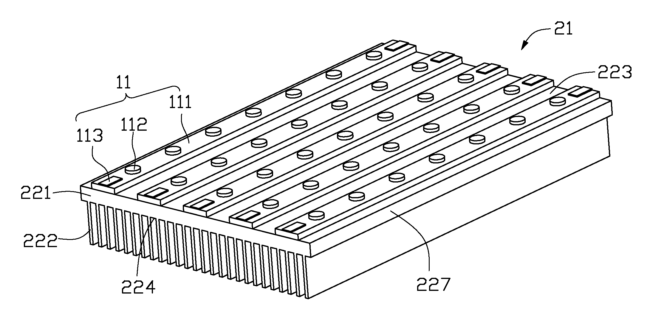
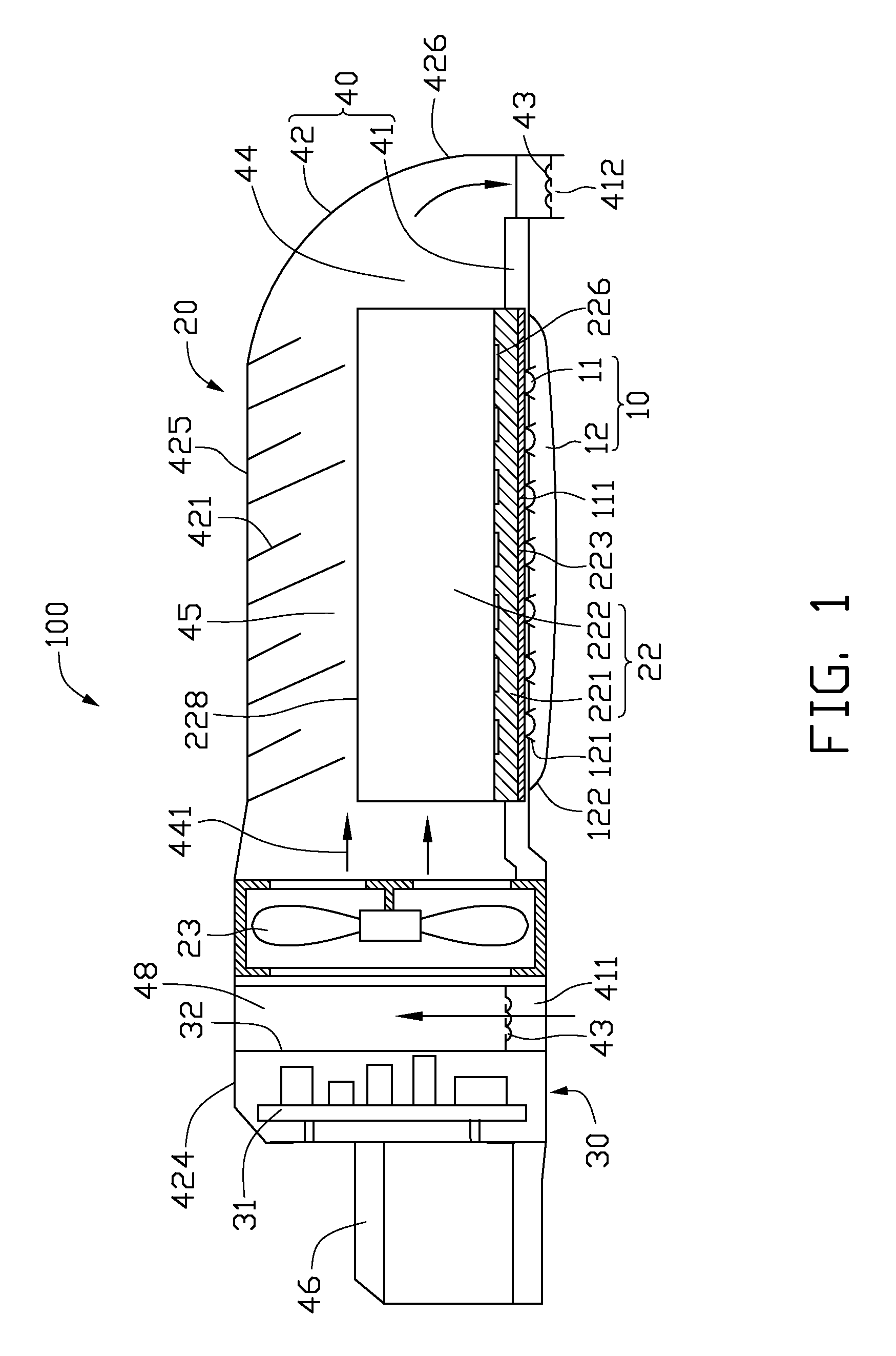
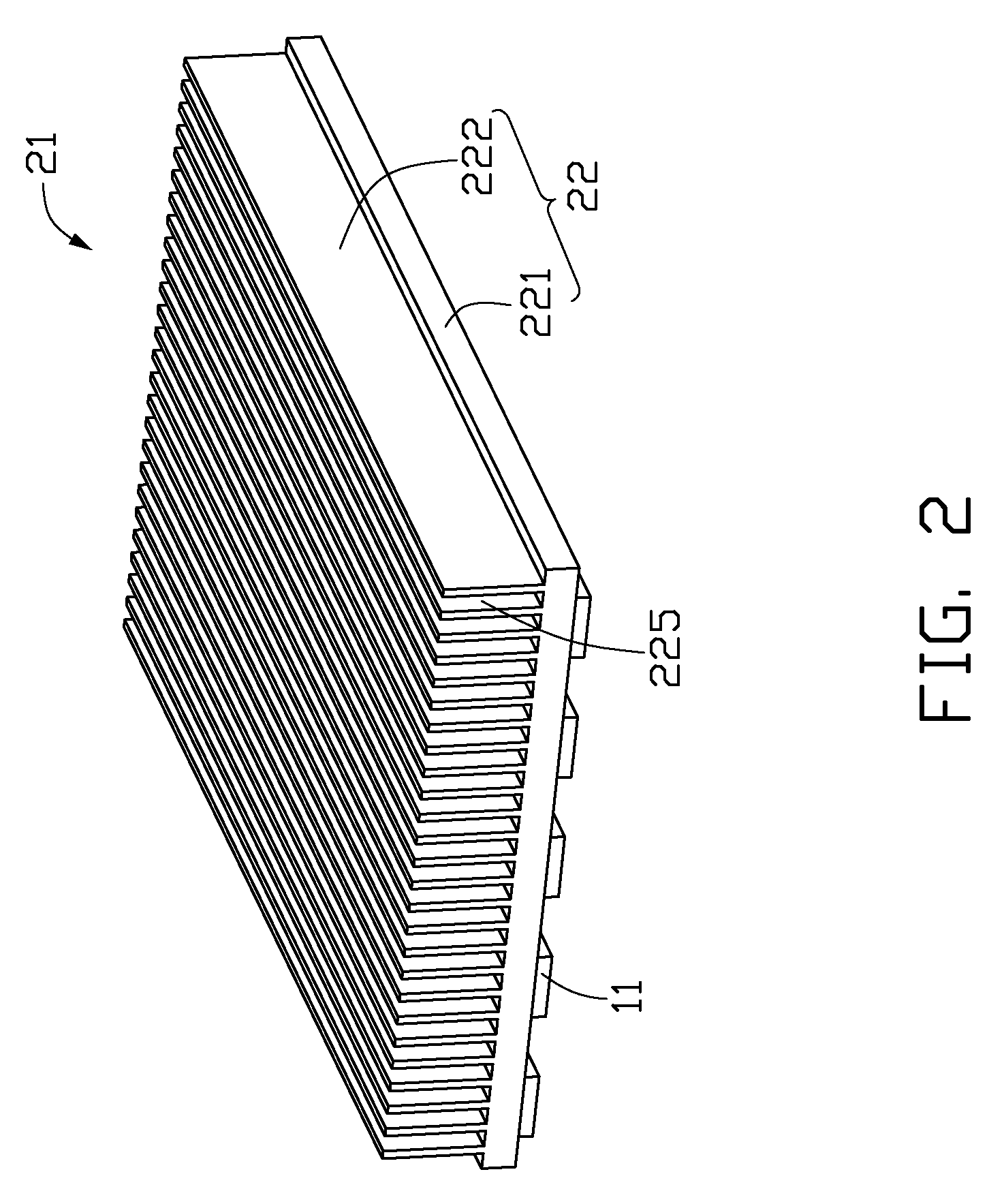
[0016]FIG. 1 is a cross-sectional view of an LED illumination device 100 in accordance with an exemplary embodiment of the present invention. The LED illumination device 100 includes a lamp housing 40, a heat dissipating module 20 received in the lamp housing 40, a light-emitting module 10 received in the lamp housing 40 and arranged under the heat dissipating module 20, and an electrical module 30 located at one end of the lamp housing 40.

[0017]The lamp housing 40 has a front end where the electrical module 30 is located and a rear end opposite to the front end. A connecting head 46 is provided at the front end of the lamp housing 40 so that, for example, when the LED illumination device 100 serves as a street lamp, the LED illumination device 100 can be attached to a lamp post via the connecting head 46. The lamp housing 40 defines therein a chamber 44 for accommodating the heat dissipating module 20 and the light-emitting module 10 therein. The lamp housing 40 includes a lamp bas...


PUM


Abstract

An LED illumination device includes a lamp housing, a heat sink, a cooling fan, and a light source. The heat sink, the cooling fan and the light source are received in the lamp housing. The heat sink includes a base and a plurality of fins extending from the base. The light source is attached to the base of the heat sink. The cooling fan causes ambient air to enter into the lamp housing and flow through the heat sink. A plurality of air-disturbing plates extends from the lamp housing towards the heat sink. The air-disturbing plates disturb the air in the lamp housing and guide the disturbed air into air passageways defined between adjacent fins of the heat sink.

Description

BACKGROUND[0001]1. Technical Field[0002]The disclosure generally relates to LED illumination devices, and particularly to an LED illumination device with a high heat dissipating efficiency.[0003]2. Description of Related Art[0004]In recent years, LEDs are preferred for use in illumination devices rather than CCFLs (cold cathode fluorescent lamps) due to their excellent properties, including high brightness, long lifespan, wide color range, and etc. For an LED, about eighty percents of the power consumed thereby is converted into heat. Therefore, a heat dissipation device is necessary for timely and adequately removing the heat generated by the LED.[0005]Conventional heat dissipation devices, such as heat sinks, are usually made of copper, aluminum, or their alloy, and have a relatively higher heat conductivity coefficient. The heat sink generally includes a base attached to the LED illumination device and a plurality of fins extending from the base for increasing a heat dissipating ...

Claims


Application Information

Patent Timeline
IPC IPC(8): F21V29/00
CPCF21V29/02F21W2131/103F21Y2101/02F21V29/763H01L2924/0002F21S8/086H01L2924/00F21Y2115/10F21V29/00F21V29/673F21V29/74F21V29/745
Inventor LIU, TAY-JIAN
Owner HON HAI PRECISION IND CO LTD
Why Eureka
Try Eureka