Optical modulator for higher-order modulation

a technology of optical modulators and optical modulators, applied in the field of optical communication equipment, can solve the problems of ineffective cost, high complexity of optics and electronics involved in the implementation of prior-art higher-order optical modulators, and inapplicability of those optical modulators

Active Publication Date: 2009-12-31
ALCATEL LUCENT SAS
View PDF7 Cites 59 Cited by
  • Summary
  • Abstract
  • Description
  • Claims
  • Application Information

AI Technical Summary

Problems solved by technology

As a result, the overall complexity of the optics and electronics involved in the implementation of prior-art higher-order optical modulators is relatively high.
Disadvantageously, this complexity renders those optical modulators impractical and / or cost ineffective.

Method used


Image

  • Optical modulator for higher-order modulation
  • Optical modulator for higher-order modulation
  • Optical modulator for higher-order modulation

Examples


Embodiment Construction

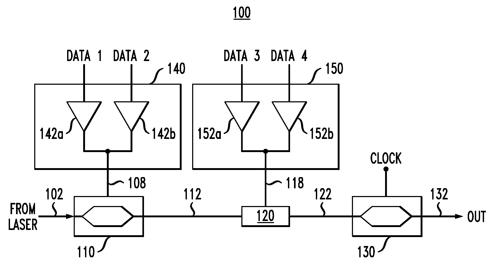
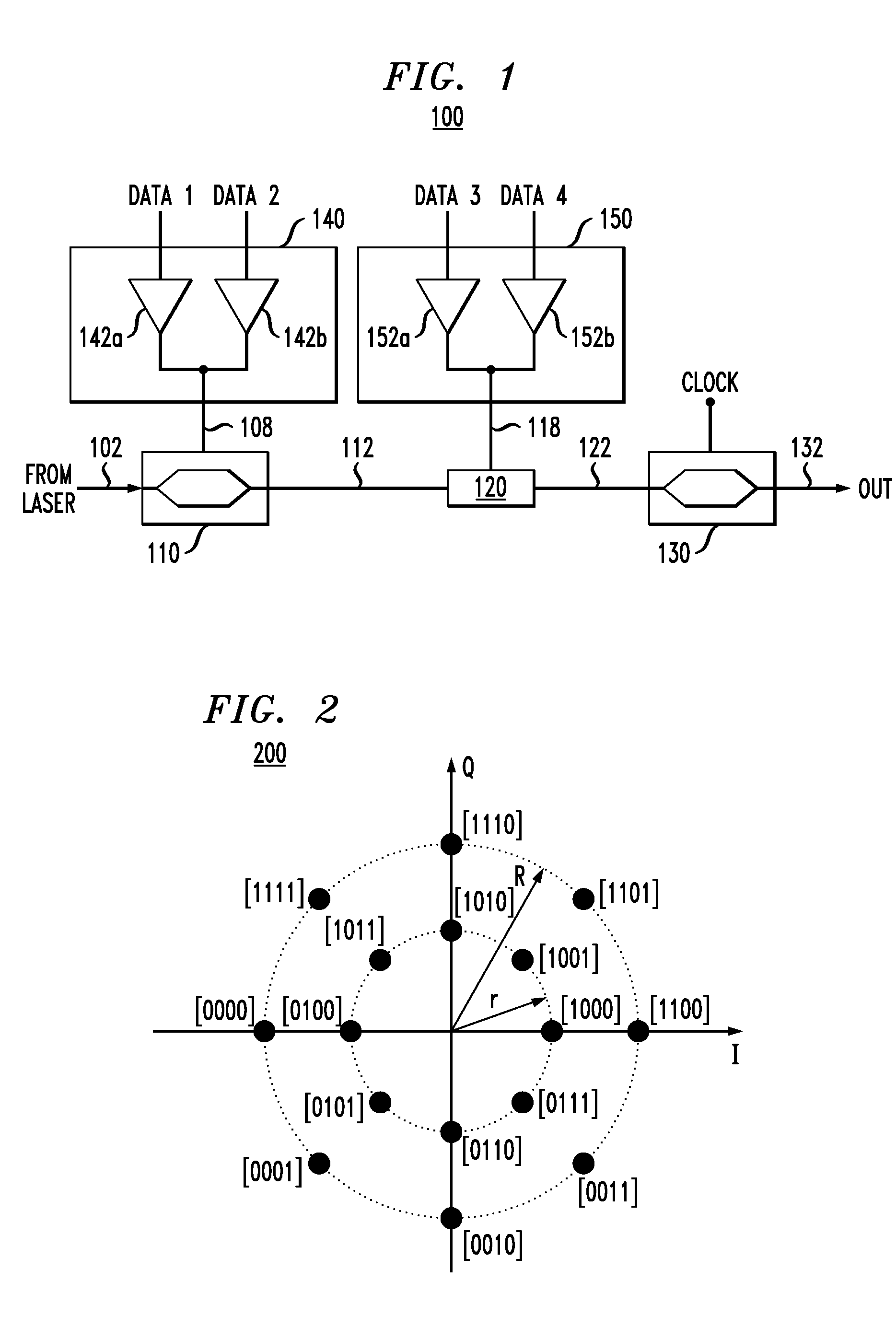
[0021]FIG. 1 shows a block diagram of a higher-order optical modulator 100 according to one embodiment of the invention. Modulator 100 receives four electrical binary signals Data 1 . . . Data 4 and generates a corresponding modulated optical output signal 132. Signal 132 can be classified as a 2-ASK / 8-PSK signal, where the acronyms 2-ASK and 8-PSK stand for binary amplitude-shift keying and 8-ary phase-shift keying, respectively.

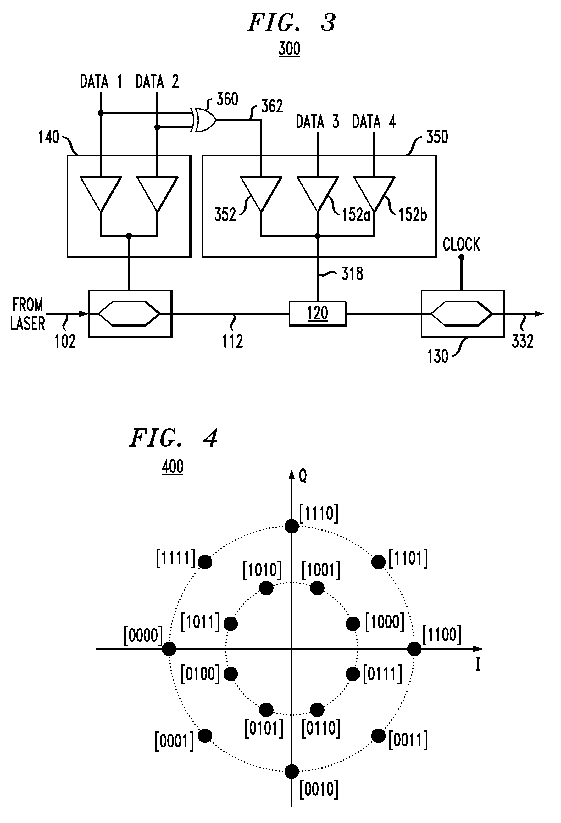
[0022]FIG. 2 graphically shows a star 16-QAM constellation 200 corresponding to signal 132. Constellation 200 has (i) eight constellation points arranged on a circle of radius r and (ii) eight constellation points arranged on a circle of radius R, where R>r. The angular separation between adjacent constellation points on each of the circles is 45 degrees. Four constellation points of constellation 200 fall on the in-phase (I) axis, and four other constellation points fall on the quadrature-phase (Q) axis. The bracketed binary values placed next to each cons...


PUM


Abstract

According to one embodiment of the invention, a 16-QAM optical modulator has a Mach-Zehnder modulator (MZM) coupled to a drive circuit that drives the MZM based on two electrical binary signals. The output of the MZM corresponds to an intermediary constellation consisting of four constellation points arranged on a straight line in the corresponding in-phase/quadrature-phase (I-Q) plane. Two of these constellation points correspond to a zero phase, and the remaining two constellation points correspond to a phase of π radian. The 16-QAM optical modulator further has a phase shifter that modulates the output of the MZM based on two additional electrical binary signals. The resulting optical output signal corresponds to a star 16-QAM constellation, which is produced by incremental rotation of the intermediary constellation.

Description

BACKGROUND OF THE INVENTION[0001]1. Field of the Invention[0002]The present invention relates to optical communication equipment and, more specifically, to optical modulators for generation of amplitude- and / or phase-modulated signals.[0003]2. Description of the Related Art[0004]This section introduces aspects that may help facilitate a better understanding of the invention(s). Accordingly, the statements of this section are to be read in this light and are not to be understood as admissions about what is in the prior art or what is not in the prior art.[0005]The ever-increasing demand for transmission capacity and a variety of limitations on spectral bandwidth in optical communication systems bring about the use of “spectrally efficient” modulation formats. Such modulation formats are generally based on higher-order optical modulation, e.g., 8-ary and higher QAM (quadrature amplitude modulation) and APSK (amplitude- and phase-shift keying). Various subspecies of QAM and APSK are de...

Claims


Application Information

Patent Timeline
Patent Type & Authority Applications(United States)
IPC IPC(8): H04B10/04
CPCH04B10/505H04B10/5561H04B10/541H04B10/532G02B6/12G02F1/21G02F2/00
Inventor WINZER, PETER J.
Owner ALCATEL LUCENT SAS
Why Eureka
Try Eureka