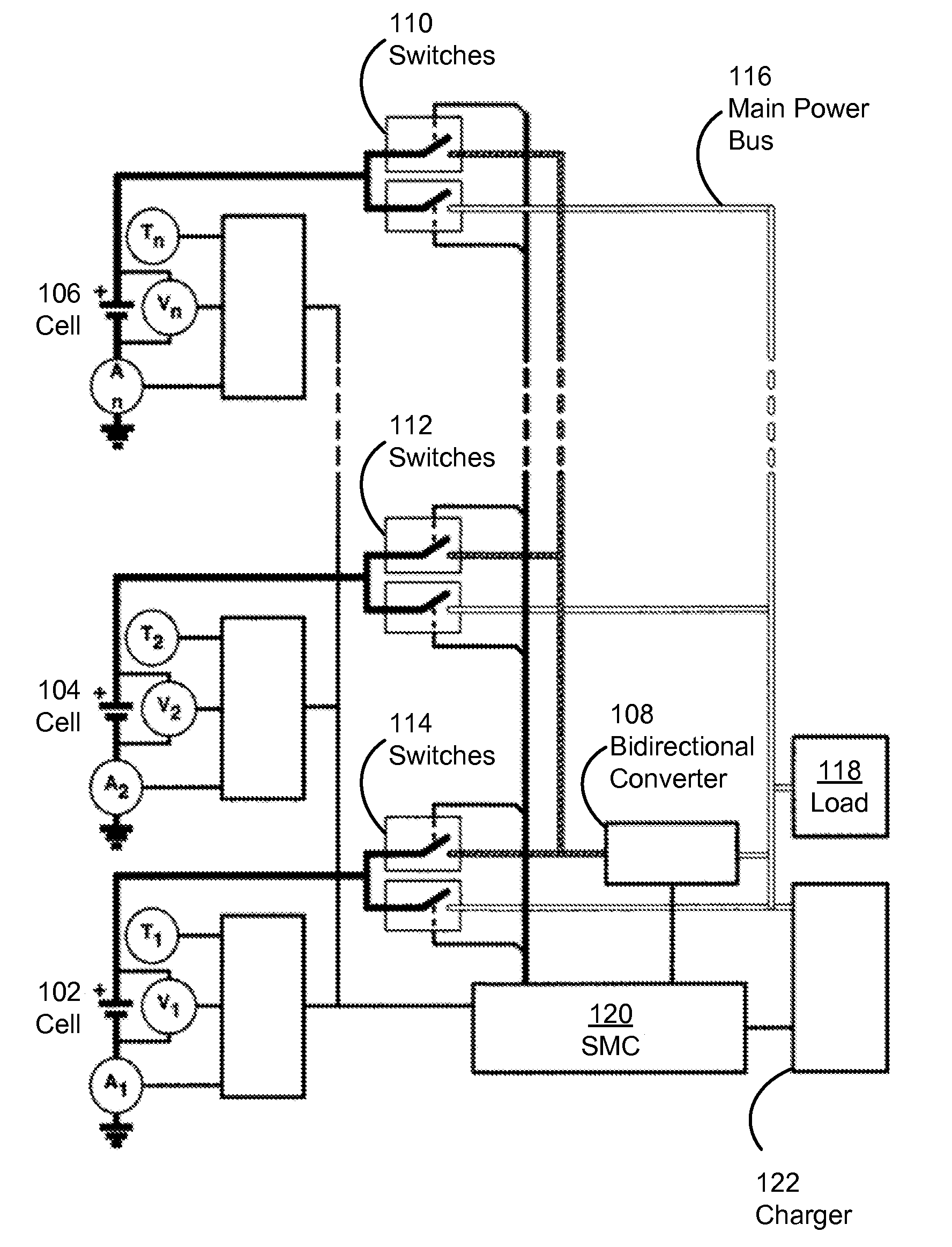
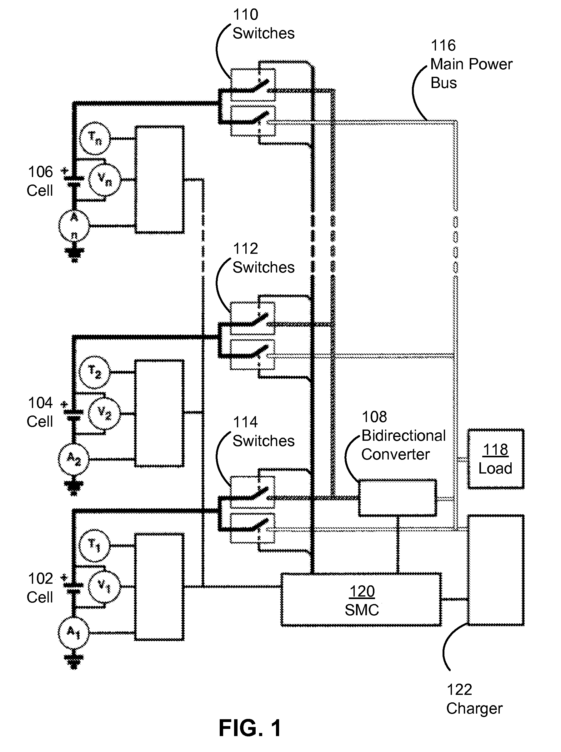
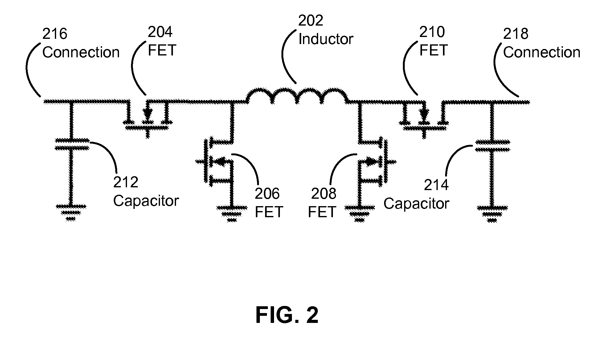
Parallel battery architecture with shared bidirectional converter

a bidirectional converter and parallel battery technology, applied in the field of power sources, can solve the problems of only accurate open circuit voltage measurement, difficult calibration of existing battery pack architectures, and difficulty in determining the state of charge or capacity of cells, and achieve the effect of facilitating cell calibration

Active Publication Date: 2009-12-31
APPLE INC
View PDF6 Cites 88 Cited by
  • Summary
  • Abstract
  • Description
  • Claims
  • Application Information

AI Technical Summary

Benefits of technology

[0025](iv) facilitating th

Problems solved by technology

However, existing battery pack architectures have a number of drawbacks.
First, a cell's state-of-charge or capacity may be difficult to calibrate.
However, open circuit voltage measurements may only be accurate when the pack is not being charged or discharged, which can be difficult for battery packs that discharge a small amount of current when at rest.
A second disadvantage relates to cell balancing.
An imbalanced battery pack may have reduced capacity, because the cell with the highest state-of-charge terminates the charging cycle and cells with lower state-of-charge never get fully charged.
Battery packs identified as too far out of b

Method used


Image

  • Parallel battery architecture with shared bidirectional converter
  • Parallel battery architecture with shared bidirectional converter
  • Parallel battery architecture with shared bidirectional converter

Examples


Embodiment Construction

[0035]The following description is presented to enable any person skilled in the art to make and use the embodiments, and is provided in the context of a particular application and its requirements. Various modifications to the disclosed embodiments will be readily apparent to those skilled in the art, and the general principles defined herein may be applied to other embodiments and applications without departing from the spirit and scope of the present disclosure. Thus, the present invention is not limited to the embodiments shown, but is to be accorded the widest scope consistent with the principles and features disclosed herein.

[0036]The data structures and code described in this detailed description are typically stored on a computer-readable storage medium, which may be any device or medium that can store code and / or data for use by a computer system. The computer-readable storage medium includes, but is not limited to, volatile memory, non-volatile memory, magnetic and optical...


PUM

PropertyMeasurementUnit
Timeaaaaaaaaaa
Poweraaaaaaaaaa
Electric potential / voltageaaaaaaaaaa

Abstract

Some embodiments provide a system that provides a power source. The power source includes a set of cells and a main power bus configured to connect the set of cells in a parallel configuration. The power source also includes a bidirectional converter configured to connect to one cell from the set of cells at a time. Finally, the power source includes a set of switches configured to switch each cell in the set of cells to one of the main power bus and the bidirectional converter.

Description

RELATED APPLICATION[0001]This application is a continuation-in-part application of a pending U.S. application, entitled “Power Source Having a Parallel Cell Topology,” by inventors Thomas Charles Greening, Bill Athas, and Steve Charles Michalske, Ser. No. 12 / 032,513, Attorney Docket Number 189671 / US, filed 15 Feb. 2008. This application hereby claims priority under 35 U.S.C. section 120 to the above-listed patent application.BACKGROUND[0002]1. Field[0003]The present embodiments relate to power sources for electronic devices. More specifically, the present embodiments relate to a parallel battery architecture with a shared bidirectional converter.[0004]2. Related Art[0005]Typical high-powered battery designs include battery packs that contain battery cells connected in various series and parallel combinations. For example, a six-cell battery pack of lithium cells may be configured in a three in series, two in parallel (3s2p) configuration. If a single cell can provide a maximum of th...

Claims


Application Information

Patent Timeline
IPC IPC(8): H01M2/26H01M4/82H02J7/00
CPCH02M3/1582G06F1/189H01M10/482H01M10/4207H02J7/0013H01M10/441H02J2007/0067G06F1/26H01M10/052Y10T29/49108H02J7/0025Y02E60/10
Inventor GREENING, THOMAS C.ATHAS, WILLIAM C.UNGAR, P. JEFFREY
Owner APPLE INC
Why Eureka
Try Eureka