Applicator for a water jet separating apparatus

a technology of water jet separating apparatus and water jet, which is applied in the field of application, can solve the problems of inability to effectively separate water jets, so as to facilitate the healing process, prevent the propagation of pathogenic microorganisms, and facilitate the healing process.

Inactive Publication Date: 2009-12-31
HUMAN MED
View PDF16 Cites 21 Cited by
  • Summary
  • Abstract
  • Description
  • Claims
  • Application Information

AI Technical Summary

Benefits of technology

[0016]It is an object of the invention to provide an applicator which ensures the largest possible work area and shields the surroundings while at the same time being suitable for mobile use.
[0018]The new applicator eliminates the above-mentioned features of the state of the art. With the invention, all the known advantages of the water jet separation are effected with these advantages being especially that a cut can be made deep into the healthy tissue in a protected manner which can be tolerated by the patient. These advantages include, for example, the following: the use of a dynamic and pulsed water jet; the use of an abrasive separating means; the use of an antibiotic, antiseptic medium; or, the use of a temperature-controlled separating means. Here, it is especially advantageous when a vacuum is generated in the protective cover via the suction line which vacuum is preferably pulsating and stimulates the tissue. This facilitates the healing process. The special advantage of the new applicator lies in that the intervention takes place in a work chamber closed off with a vacuum therein. This draws the tissue parts by suction into the work chamber and prepares the tissue parts in an advantageous manner for the separating operation. The vacuum, however, ensures also that the blood flow of the wound or the ulcer is increased which advantageously affects the cleaning of the wound or ulcer. A special advantage, however, is that the propagation of pathogenic microorganisms is reliably prevented for the protection of the surgeon and the surroundings. This protection takes place because of the vacuum-conditioned sealing of the work chamber during the surgical procedure. The protection results, however, in that the separating liquid is controlled by the vacuum and can only discharge when the sealing of the work chamber is ensured. An additional shield is provided during the switch-off phase by a special sealing element having a novel catch flap.
[0019]The new applicator also provides a work area of increased size because the protective cover can be dimensioned, configured and arranged independently of the arrangement of the discharge nozzles and the suction openings. In this way, larger wounds or ulcer surfaces can be treated. Should a repositioning nonetheless be required, this is easily realized by the surgeon with the control of the vacuum via the bypass opening in the suction flow.

Problems solved by technology

The protection results, however, in that the separating liquid is controlled by the vacuum and can only discharge when the sealing of the work chamber is ensured.

Method used


Image

  • Applicator for a water jet separating apparatus
  • Applicator for a water jet separating apparatus
  • Applicator for a water jet separating apparatus

Examples


first embodiment

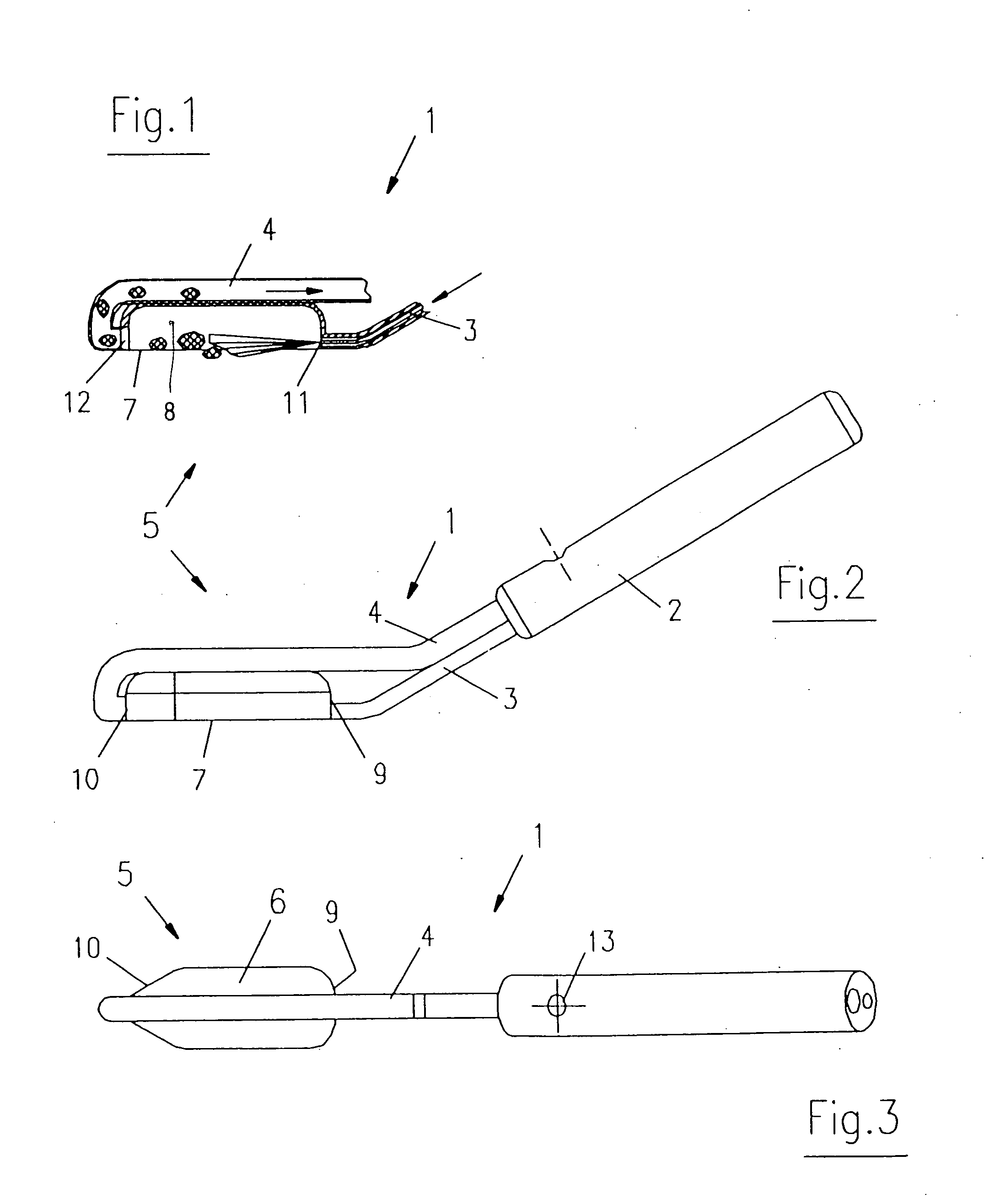
[0036]In a first embodiment as shown in FIGS. 1 to 3, the work probe 5 has a flat protective cover 6 open downwardly and closed upwardly and to the sides. The protective cover 6 has a peripherally-extending sealing edge 7 on its open side facing downwardly. The sealing edge 7 can be adapted to the greatest extent possible to the shape of the body of the patient and is preferably equipped with a special sealing material which permits an airtight closure to the body surface. In this way, a hermetically closed off work chamber 8 is formed. The protective cover 6 comprises a transparent material in order to permit viewing into the work chamber 8 from the outside and therefore onto the work area. This protective cover 6 is preferably elongated and has a lateral surface 9 close to the handpiece 2 and a lateral surface 10 remote with respect to the handpiece 2. The pressure line 3 for the water jet opens laterally into the lateral surface 9 close to the handpiece 2 and forms a discharge no...

second embodiment

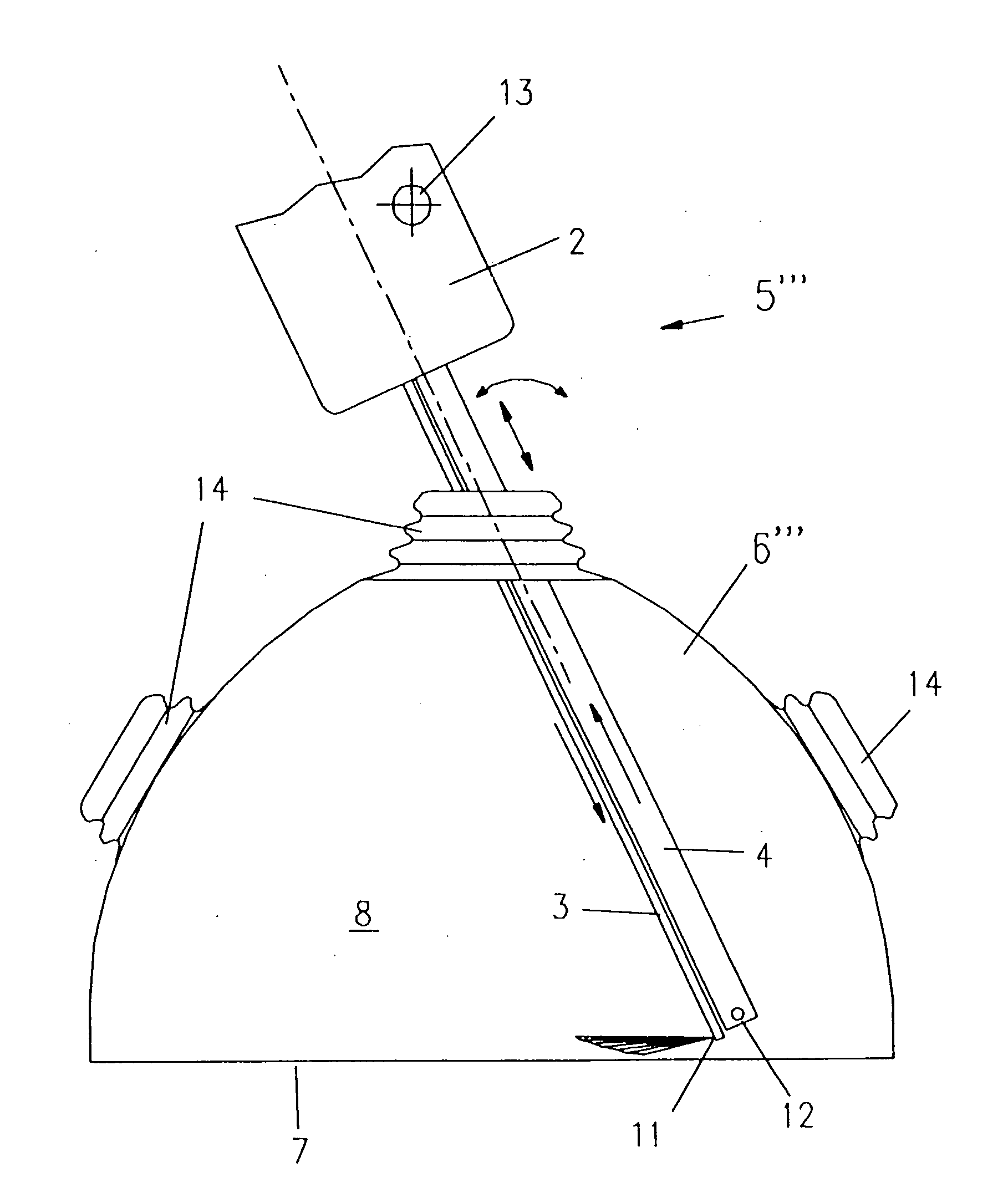
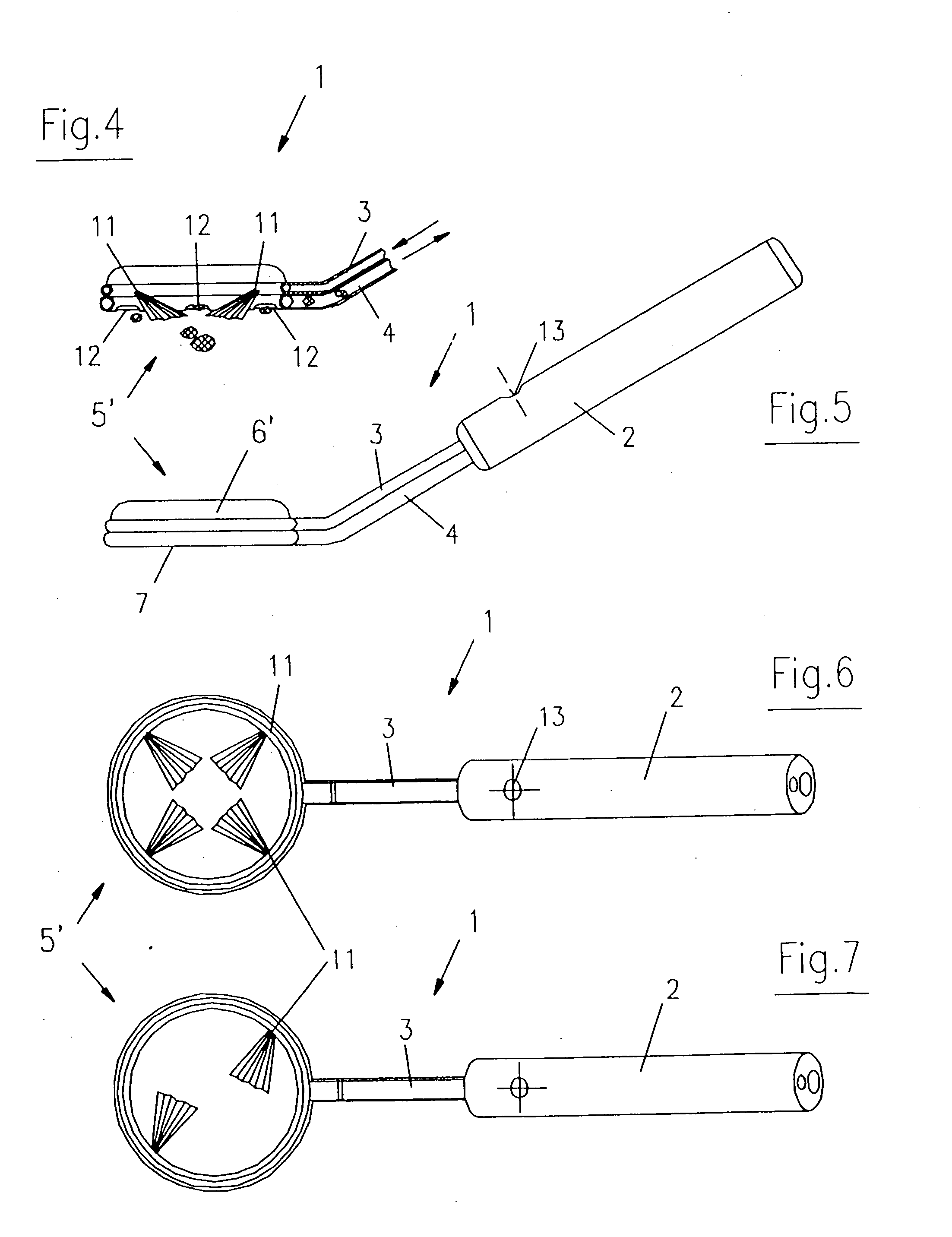
[0037]As shown in FIGS. 4 to 7, in the second embodiment, the work probe 5′ has, in the same manner, a handpiece 2 having a pressure line 3, a suction line 4 and a protective cover 6′ having a sealing edge 7. The pressure line 3 and the suction line 4 are, in turn, led laterally to the protective cover 6′. The protective cover 6′ is configured to be round when viewed in cross section and the pressure line 3 and the suction line 4 are guided on the periphery of the protective cover 6′. The peripherally-extending segment of the suction line 4 is disposed at the lowest plane and the pressure line 3 is disposed in the plane of the protective cover 6′ lying thereabove. For this purpose, preferably several suction openings 12 are uniformly distributed in the peripherally-extending segment of the suction line 4. As shown in FIG. 6, the pressure line 3 lying thereabove has four discharge nozzles 11, which are arranged uniformly offset, so that always two of the discharge nozzles 11 lie oppo...

third embodiment

[0041]The modified work probe 5″ of the third embodiment is shown in FIGS. 10 and 11 and has, in turn, a cylindrical protective cover 6″ which is made of a transparent material and which accommodates and encloses the pressure line 3 and the suction line 4 along the length in the distal region of the applicator 1. The protective cover 6″ is connected tightly to the handle 2. The pressure line 3 and the suction line 4 are arranged at a radial distance with respect to each other and to the cylindrical protective cover 6″ in such a manner that the ends of the pressure line 3 and the suction line 4 are arranged with respect to each other at the distal region at a largest radial distance. The pressure line 3 is closed at the end face with the discharge nozzle 11 being arranged radially at the outermost end of the pressure line 3. The discharge nozzle 11 is preferably a flat nozzle. The discharge nozzle 11 is directed in the direction of the end of the suction line 4. This end of the sucti...


PUM


Abstract

In order to provide a work area that is as large as possible, and to shield off the environment, and in order to simultaneously provide for a mobile application, the discharge nozzle (11) and the suction opening (12) are disposed in a protective cover (6, 6′, 6″, 6′″). The protective cover (6, 6′, 6″, 6′″) and the body parts of the patient conjointly form a defined vacuum-sealed work chamber (8). The protective cover is made of a transparent material.

Description

CROSS REFERENCE TO RELATED APPLICATIONS[0001]This application is a continuation application of international patent application PCT / DE 2007 / 002057, filed Nov. 14, 2007, designating the United States and claiming priority from German application 20 2006 018 986.6, filed Dec. 16, 2006, and the entire content of both applications is incorporated herein by reference.FIELD OF THE INVENTION[0002]The invention relates to an applicator for a water jet separating apparatus especially for treating wounds and abscesses.BACKGROUND OF THE INVENTION[0003]Wounds and abscesses are injuries to the skin and heal best when: an adequate blood flow is present for self cleaning; the bacteria, which have developed in the ulcer, are destroyed or are removed; and, the upper epidermis of the tissue is configured to have sharp edges to facilitate better healing. For smaller wounds, it is only necessary to clean and disinfect in order to satisfy these conditions.[0004]Larger wounds and ulcers have, as a rule, ...

Claims


Application Information

Patent Timeline
Patent Type & Authority Applications(United States)
IPC IPC(8): A61M1/00
CPCA61B17/3203A61B17/32037A61H9/0028A61B19/38A61M1/0088A61M3/0287A61H35/00A61B2017/00761A61B90/40A61M3/0216A61M2205/3344A61M1/7411A61M1/85A61M1/916A61M1/966
Inventor KENSY, ARNDWINKLER, KONRAD-WENZELNIKLAS, FRANKPEULECKE, THOMASRUNOW, ANDREASBEHNERT, FREDSCHLEE, GERNOT
Owner HUMAN MED
Why Eureka
Try Eureka