[0005]A fixation plate is provided for tying together or fixing together two or more adjacent
cervical vertebrae C2 through T1. The fixation plate can have any of three basic configurations, the first of which resembles an H shape or a series of stacked H shapes, the second of which resembles an A shape or a series of stacked A shapes, and the third of which resembles an X shape or a series of stacked X shapes. Each of the fixation plates is curved or angles about the axial plate through the two adjacent and joined vertebrae at an angle □ that varies with the location on the cervical column and with the number of vertebrae fixed to the plate. The angle is preferably selected to follow the average
spinal curvature for the appropriate cervical location, but the angle can be varied according to an individual's specific
spinal curvature, and preferably the angle is custom bent prior to use to match the
spinal curvature of the patient / user. Each of the fixation plates is also curved or angled at an angle α about the
sagittal plane in the anterior direction so the lateral portions of the fixation plate conform to the lateral curvature of the vertebrae and thus allow a more conforming fit of the fixation plate to the vertebrae and a lower profile plate that can fit beneath the tissue covering the anterior of the spine and thereby reduce
irritation of abutting and adjacent tissue.
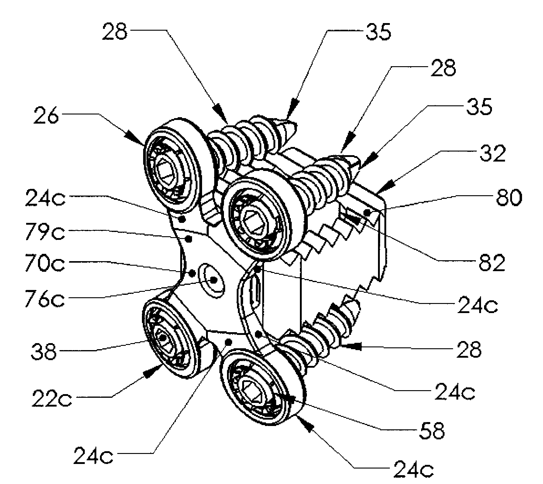
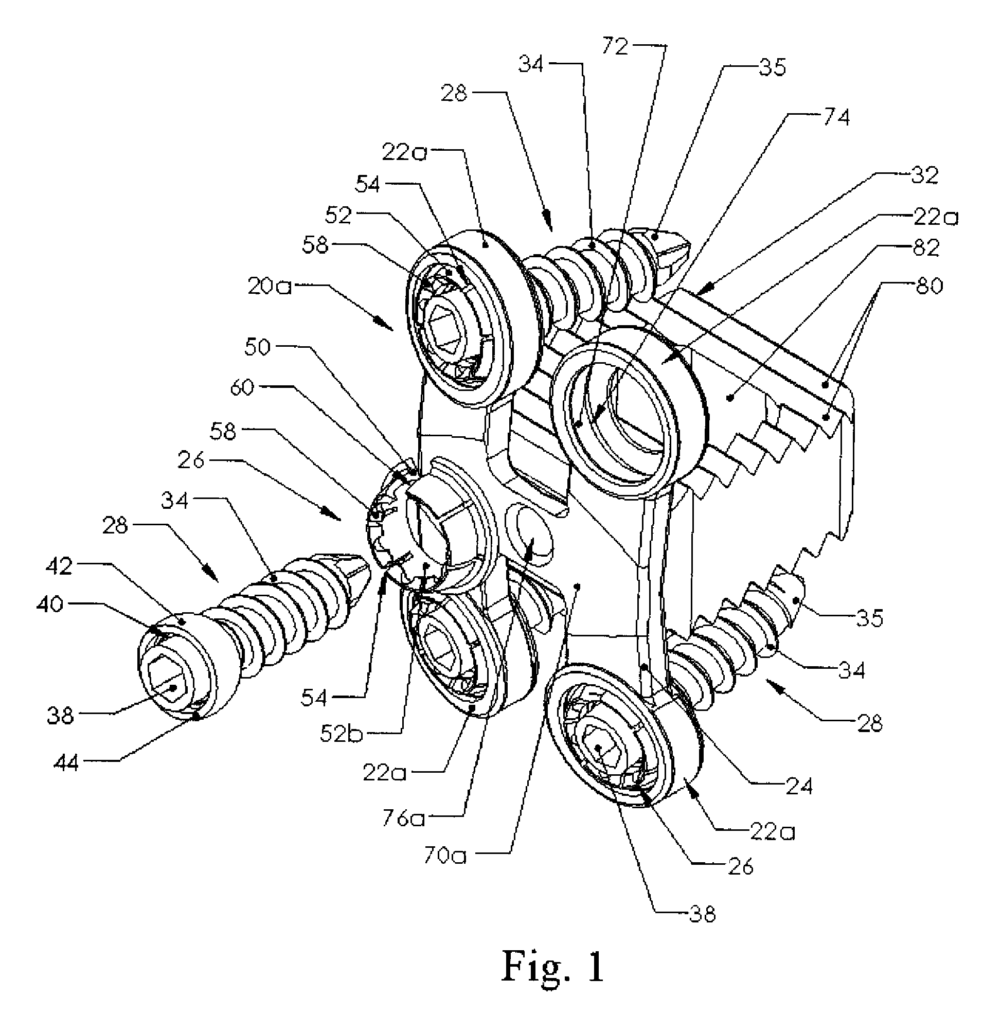
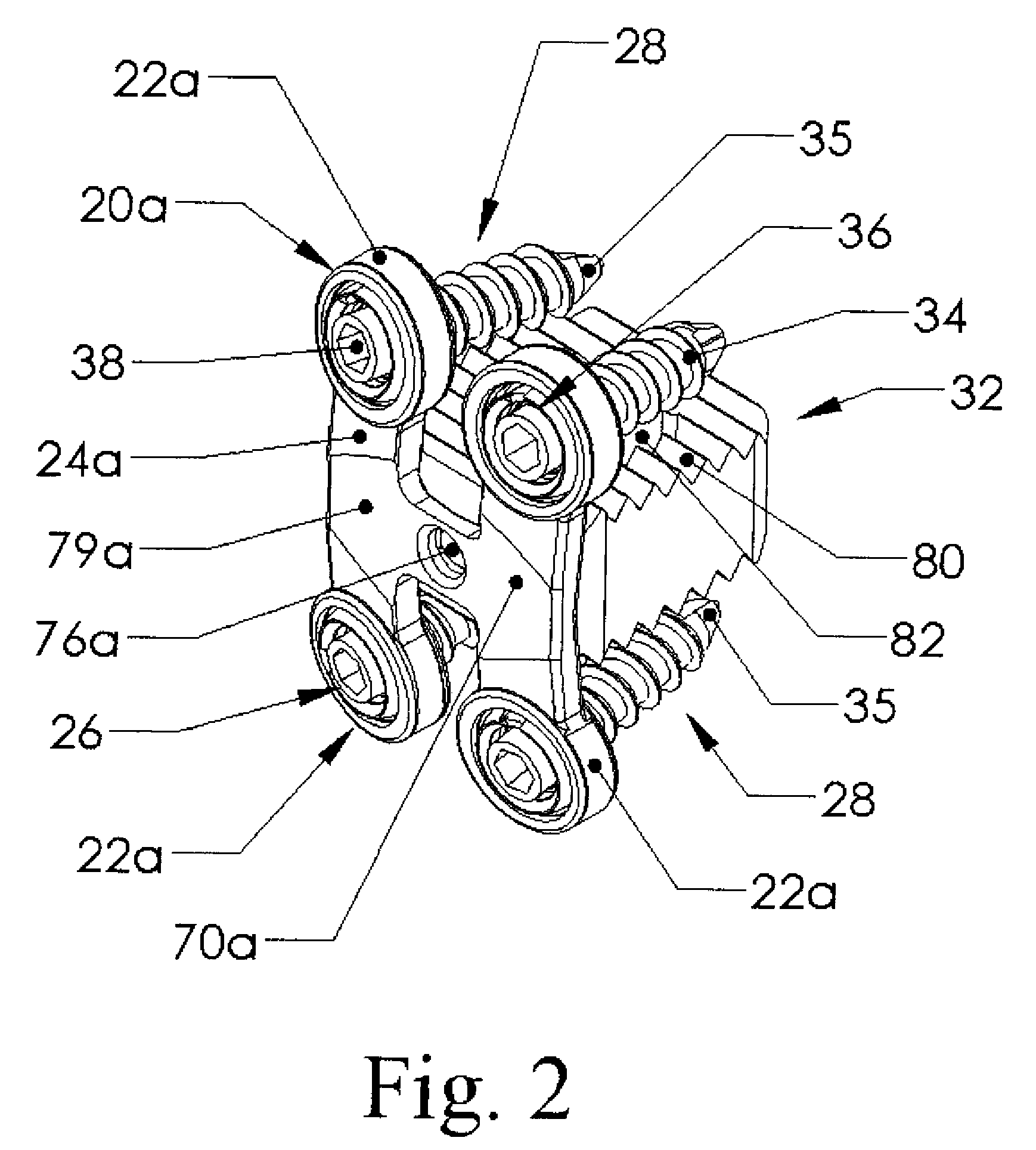
[0006]Each fixation plate has a socket with a curved surface configured to accommodate a bushing having a base with an outwardly extending flange. The bone screw passes through and is held by the bushing. The bushing's flange fits inside an annular recess in a socket of the fixation plate but the recess is slightly larger than the flange so the bushing can tilt until the flange hits the recess. By varying the dimensions of the flange on the bushing and the recess in the socket varying amounts of angulation or angular tilt of the bushing and bone screw can be accommodated. The annular bushing has a slot through it so it can be compressed and inserted into the socket and recess. The annular bushing is thus advantageously a split bushing.
[0008]The
screw head can thus rotate inside the bushing, which rotates the socket to allow positioning adjustment of the screw relative to the fixation plate. When the plate is installed, the limited rotation allowed by the
screw head, bushing and socket allow
impact forces to be accommodated and provide some flexibility in absorbing the
impact accompanying those forces. In particular, the split bushing can rotate, translate and distort to a limited degree in absorbing and transmitting forces from the bone screw to the fixation plate.
[0009]The fixation plate is not a
solid rectangular plate but has the sockets on the ends of legs. The legs are stiff, but provide more flexibility than does the continuous plate, further providing flexibility and limited motion sufficient to accommodate
impact forces. Fixation plates having an H shape, an X shape and an A shape are believed suitable.
[0010]The legs extend from the cross-members of these H and A shaped fixation plates, and from the cross member formed by the four intersecting legs of the X shaped fixation plate. The cross-member and optionally portions of the adjoining legs can be flattened on the posterior side to reduce the profile of the fixation plate and to reduce
irritation of adjacent tissue. The flattening also reduces stiffness and increases flexibility. The underside, or anterior spinal sides of the cross-member and optionally the anterior side of the adjoining portion of the legs can also be flattened to further reduce the profile and / or to adjust the flexibility of the legs and the sockets at the ends of the legs. The H and X-shaped fixation plates can be joined together at common sockets to provide multi-level fixation across more than one vertebral
disc space as described in detail herein.
[0012]In further variations, the continuously curved spherical outer surface of the bone screw head, and the inner and outer curved surfaces of the bushing have a common center of curvature. Advantageously, the curved spherical outer surface of the bone screw ends at a top edge, and the bushing segments have flanges which resiliently extend over the top edge of the bone screw to restrain removal of the bone screw from the bushing. Further, the bone screw can have an annular recess in the head located outward of the driving socket and encircling the driving socket, to help with removal of the bone screw. Additionally, a
vertebral body replacement can be optionally fastened to the fixation plate, before or after the plate is affixed to the vertebrae.

