Dynamic Rod

a technology of dynamic rods and rods, applied in the field of dynamic rods, can solve the problems of inability to create, limited or no ability to create, and competitive systems by their design do not allow multiple level soft fixation, etc., to achieve multi-level soft stabilization, increase or decrease stiffness, and facilitate the span of multiple vertebral levels

Inactive Publication Date: 2009-12-31
SONGER MARCUS +1
View PDF16 Cites 118 Cited by
  • Summary
  • Abstract
  • Description
  • Claims
  • Application Information

AI Technical Summary

Benefits of technology

[0009]The system described herein has many benefits over earlier soft fixation systems. This system can easily span multiple vertebral levels since multiple pedicle screws can be attached to one elongated fixation member thereby providing multi-level soft stabilization even during a minimally invasive surgery. Competitive systems by their design do not allow multiple level soft fixation. The elongated member in this system can be contoured or bent anywhere along the rod whereas other soft stabilization systems have limited or no ability to create an even bend unless it is built into the system initially. There are no stress concentrations on the elongated fixation member since this member is a combination of continuous materials vs. the multiple components of rods in the prior art which are assembled and have combinations of stiff and elastic combinations along the rod.
[0010]Other benefits include: consistent stiffness along the length of the elongated fixation member thereby providing flexibility in fixing screws anywhere along this member with no required distance between the screws. Also, various outer member sleeve sizes can accommodate to various sizes of yolks making it potentially compatible with many different pedicle screw systems. Further, the elongated fixation member can be inserted in a minimally invasive fashion—pericutaneously. All other systems have to be inserted into the yolk of a pedicle screw at specific points, usually under direct vision. Since the rod is made of the combination of t...

Problems solved by technology

The system further comprises at least two specialized bone anchors designed typically in the form of pedicle screws to restrain the outer elongated member without compressing the inner elongated member thereby causing undesired wear of components.
Competitive systems by...

Method used


Image

  • Dynamic Rod
  • Dynamic Rod
  • Dynamic Rod

Examples


Embodiment Construction

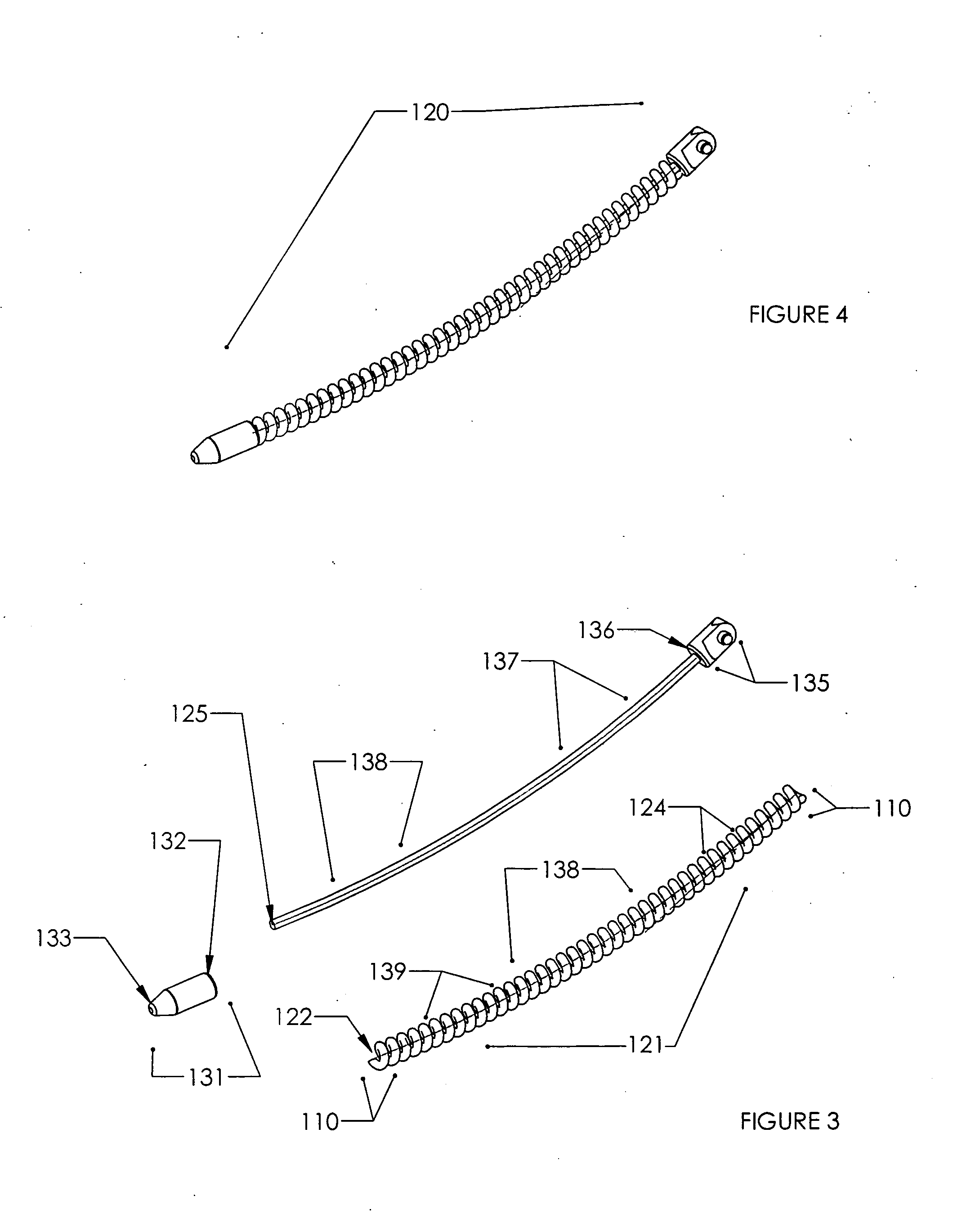
[0045]This disclosure describes a spinal stabilization system comprising a specialized elongated fixation member and at least two specialized bone fasteners designed to restrain the elongated fixation member thereby softly stabilizing the associated spinal segments. The elongated fixation member comprises an outer elongated member surrounding an inner elongated member. The specialized bone fasteners / anchors restrain the outer elongated member without substantial compression on the inner member and without inhibiting translatory motion of the inner elongated member with respect to the outer member.

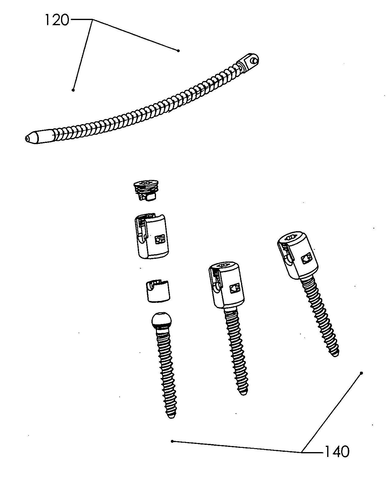
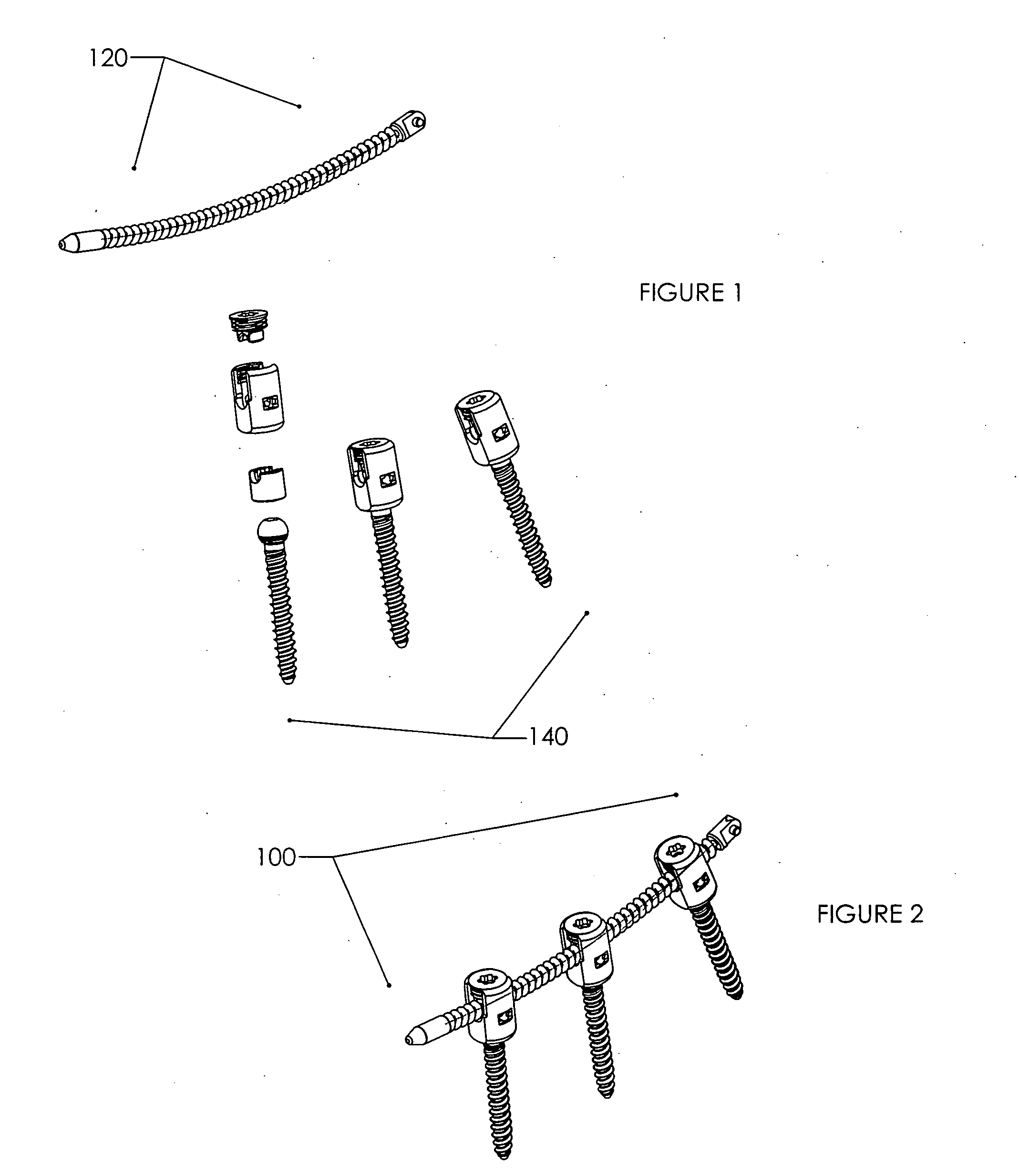
[0046]FIG. 1 illustrates a preferred embodiment of the spinal stabilization system 100 disclosed herein in a partially exploded form. The system 100 comprises an elongated stabilization member 120 and at least two fixed or polyaxial bone anchors in the form of pedicle screws 140 configured to restrain the elongated stabilization member 120. This embodiment of the fully assembled system illu...


PUM


Abstract

A spinal implant system for stabilization of the spine is disclosed comprising a pair of bone anchors, an elongate stabilization device received in the bone anchors, the stabilization device having an elongate inner stabilizing member and an outer stabilizing member disposed about the inner member and wherein said anchors are configured to inhibit translation of the outer member and to permit translation of the inner member.

Description

CROSS-REFERENCE TO RELATED APPLICATIONS[0001]The subject application is a utility application stemming from U.S. provisional application Ser. No. 61 / 043,880 filed Apr. 10, 2008 the disclosure of which is herein incorporated by reference in its entirety.FIELD OF THE INVENTION[0002]The spinal stabilization implant system disclosed herein is designed to provide a predetermined stabilization constraint to the natural spine within beneficial motion and flexibility limits.BACKGROUND OF THE INVENTION[0003]A human spine comprises a number of joints often referred to motion segments. These segments exhibit kinematics characteristic of the entire spine. The motion segments are capable of flexion, extension, lateral bending and translation. The components of each motion segment are important for the stability of the joint and each unit include two adjacent vertebrae and their apophyseal joints, the intervertebral disc, and the connecting ligamentous tissue.[0004]Components of a motion segment ...

Claims


Application Information

Patent Timeline
IPC IPC(8): A61B17/70A61B17/86
CPCA61B17/702A61B17/7028A61B17/7037A61B17/7032A61B17/7029
Inventor SONGER, MARCUSSONGER, JASON
Owner SONGER MARCUS
Why Eureka
Try Eureka