Phase behavoir analysis using a microfluidic platform

Active Publication Date: 2009-12-31
SCHLUMBERGER TECH CORP
View PDF13 Cites 19 Cited by
  • Summary
  • Abstract
  • Description
  • Claims
  • Application Information

AI Technical Summary

Problems solved by technology

Despite wide application, conventional PVT measurements suffer from several significant limitations.
Firstly, a conventional PVT analysis typically re

Method used


Image

  • Phase behavoir analysis using a microfluidic platform
  • Phase behavoir analysis using a microfluidic platform
  • Phase behavoir analysis using a microfluidic platform

Examples


Embodiment Construction

[0036]Illustrative embodiments of the invention are described below. In the interest of clarity, not all features of an actual implementation are described in this specification. It will be appreciated that in the development of any such actual embodiment, numerous implementation-specific decisions must be made to achieve the developer's specific goals, such as compliance with system-related and business-related constraints, which will vary from one implementation to another. Moreover, it will be appreciated that such a development effort might be complex and time-consuming but would nevertheless be a routine undertaking for those of ordinary skill in the art having the benefit of this disclosure. Further, like reference numbers and designations in the various drawings indicated like elements.

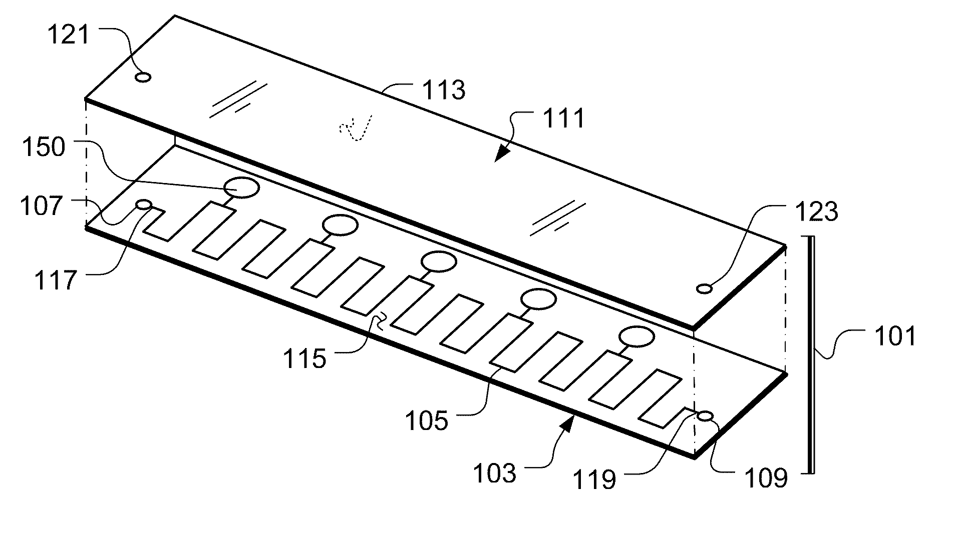
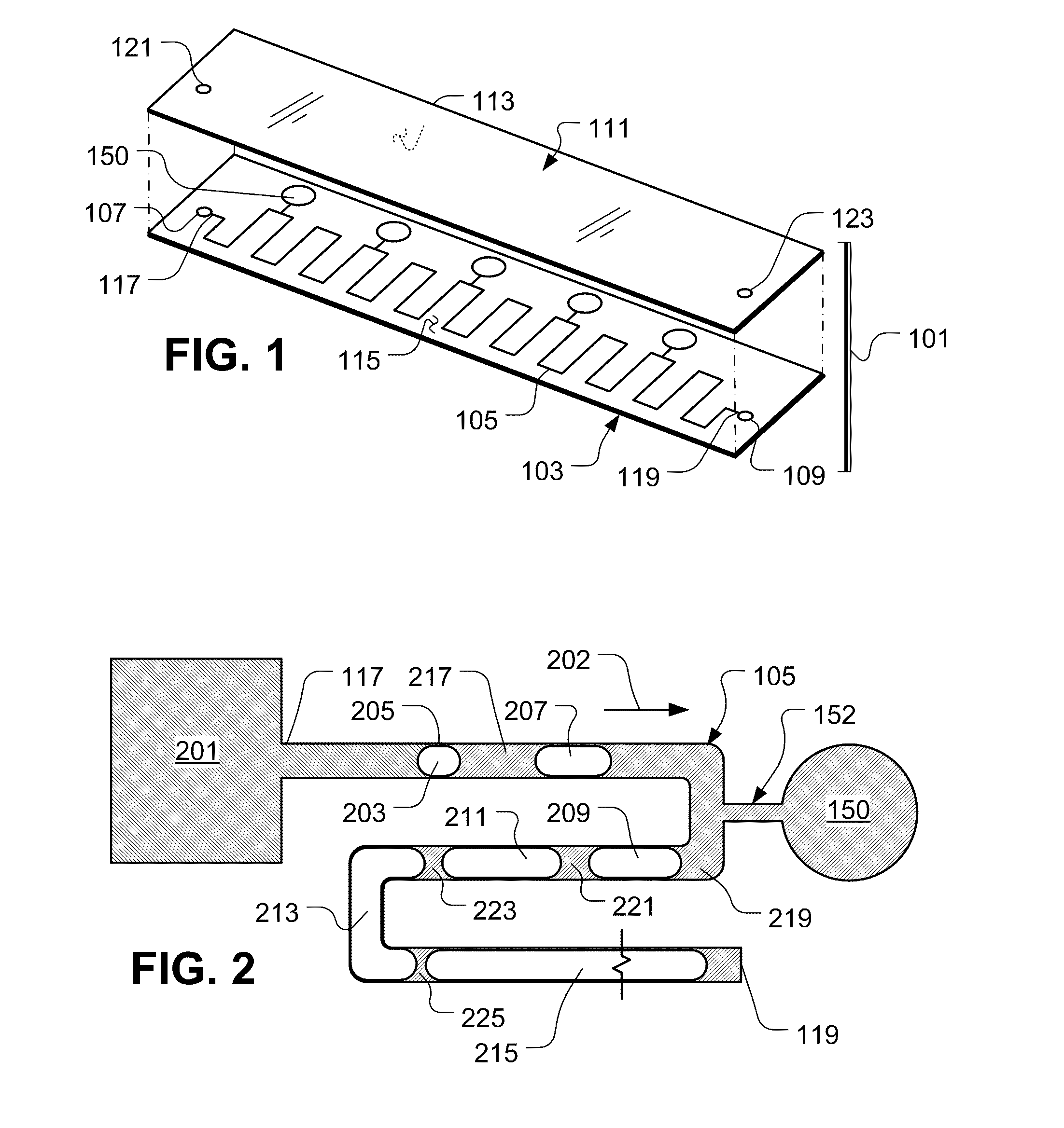
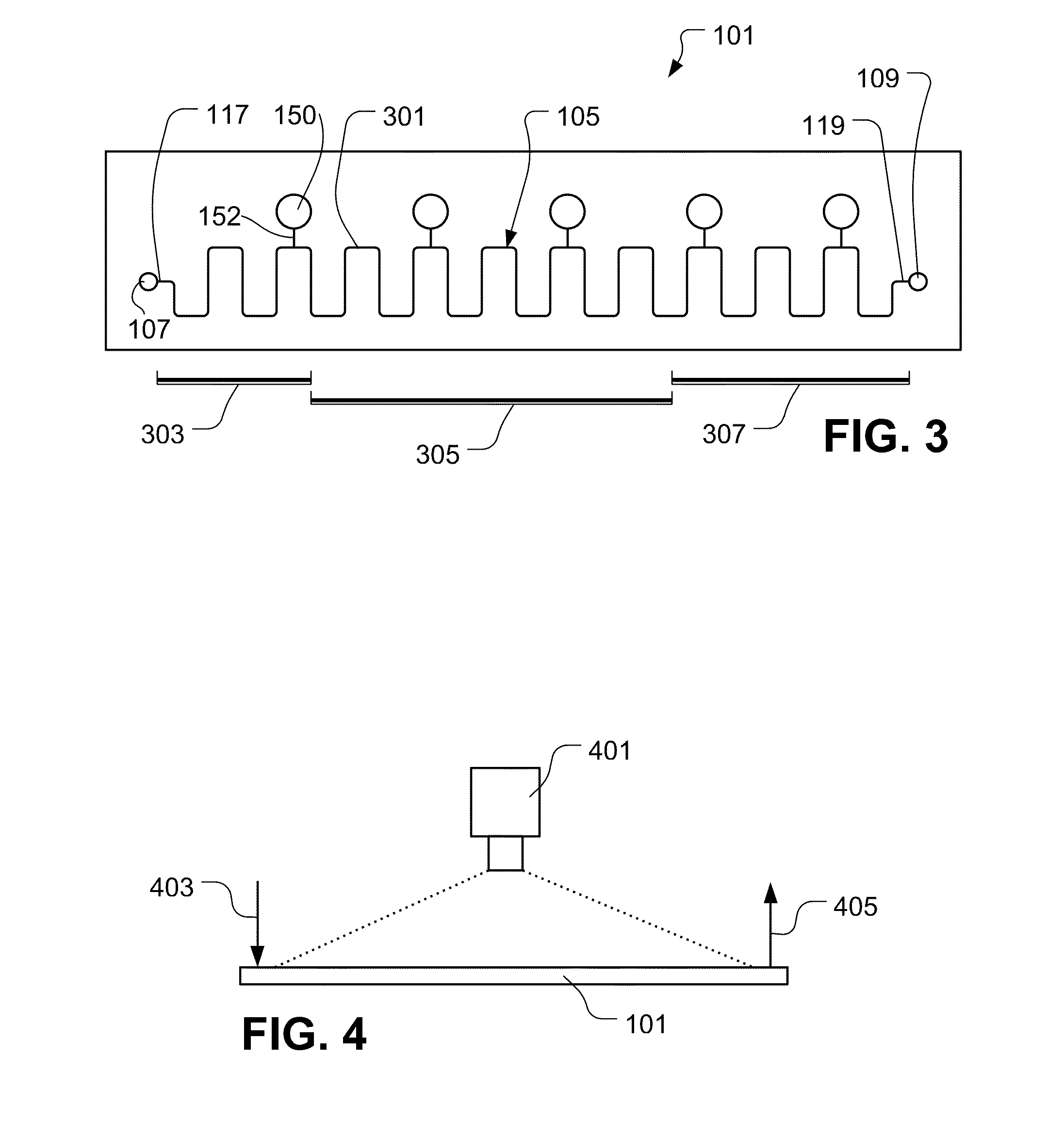
[0037]According to embodiments, techniques for measuring phase behavior of gas-liquid mixtures are provided. The techniques use a microfabricated chip made of a microchannel connected to thin S...


PUM


Abstract

Methods and related systems are described for analyzing phase properties in a microfluidic device. A fluid is introduced under pressure into microchannel, and phase states of the fluid are optically detected at a number of locations along the microchannel. Gas and liquid phases of the fluid are distinguished based on a plurality of digital images of the fluid in the microchannel. Bi-level images can be generated based on the digital images, and the fraction of liquid or gas in the fluid can be estimated versus pressure based on the bi-level images. Properties such as bubble point values and/or a phase volume distribution ratio versus pressure for the fluid are can be estimated based on the detected phase states of the fluid.

Description

CROSS-REFERENCE TO RELATED APPLICATIONS[0001]This patent application is a continuation-in-part of International Patent Application No. PCT / IB09 / 50500, filed Feb. 7, 2009, which is incorporated by reference herein.BACKGROUND OF THE INVENTION[0002]1. Field of the Invention[0003]This patent specification relates to an apparatus and method for measuring thermo-physical properties of a fluid. More particularly, the patent specification relates to an apparatus and method for analyzing phase behavior properties of a reservoir fluid flowing in a microfluidic device.[0004]2. Description of Related Art[0005]The measurement of reservoir fluid properties is a key step in the planning and development of a potential oilfield. It is often desirable to perform such measurements frequently on a producing well to provide an indication of the performance and behavior of the production process. Examples of such measurements are pressure, volume, and temperature measurements, often referred to as “PVT” ...

Claims


Application Information

Patent Timeline
IPC IPC(8): G01V1/40
CPCB01L3/502784B01L9/527B01L2300/0654B01L2300/0887B01L2400/0463B01L2400/0487G01N2035/00514G01N15/1463G01N15/1484G01N33/2823G01N2015/0011G01N2035/00148E21B49/00G01N35/08
Inventor MOSTOWFI, FARSHIDBELAHNECH, YOUNES
Owner SCHLUMBERGER TECH CORP
Why Eureka
Try Eureka