Torque measurement device and program

Inactive Publication Date: 2009-12-31
THE TOKYO ELECTRIC POWER CO INC
View PDF1 Cites 2 Cited by
  • Summary
  • Abstract
  • Description
  • Claims
  • Application Information

AI Technical Summary

Benefits of technology

[0011]The present invention detects the existence region of the pair of reflectors by determining the point which minimizes AIC of the model for the reflected light data of the rotating body, which is obtained by the reflection of the pair of reflectors provided on the surface of the rotating body having the spacing in the axial direction, and thereby a detection accuracy of the reflector positions is improved. Therefore, an accuracy of the torque calculated from the reflector

Problems solved by technology

In such a torque measurement device, extraction of the reflected light data necessary for signal processing, yes-no judgment of a proces

Method used


Image

  • Torque measurement device and program
  • Torque measurement device and program
  • Torque measurement device and program

Examples


first embodiment

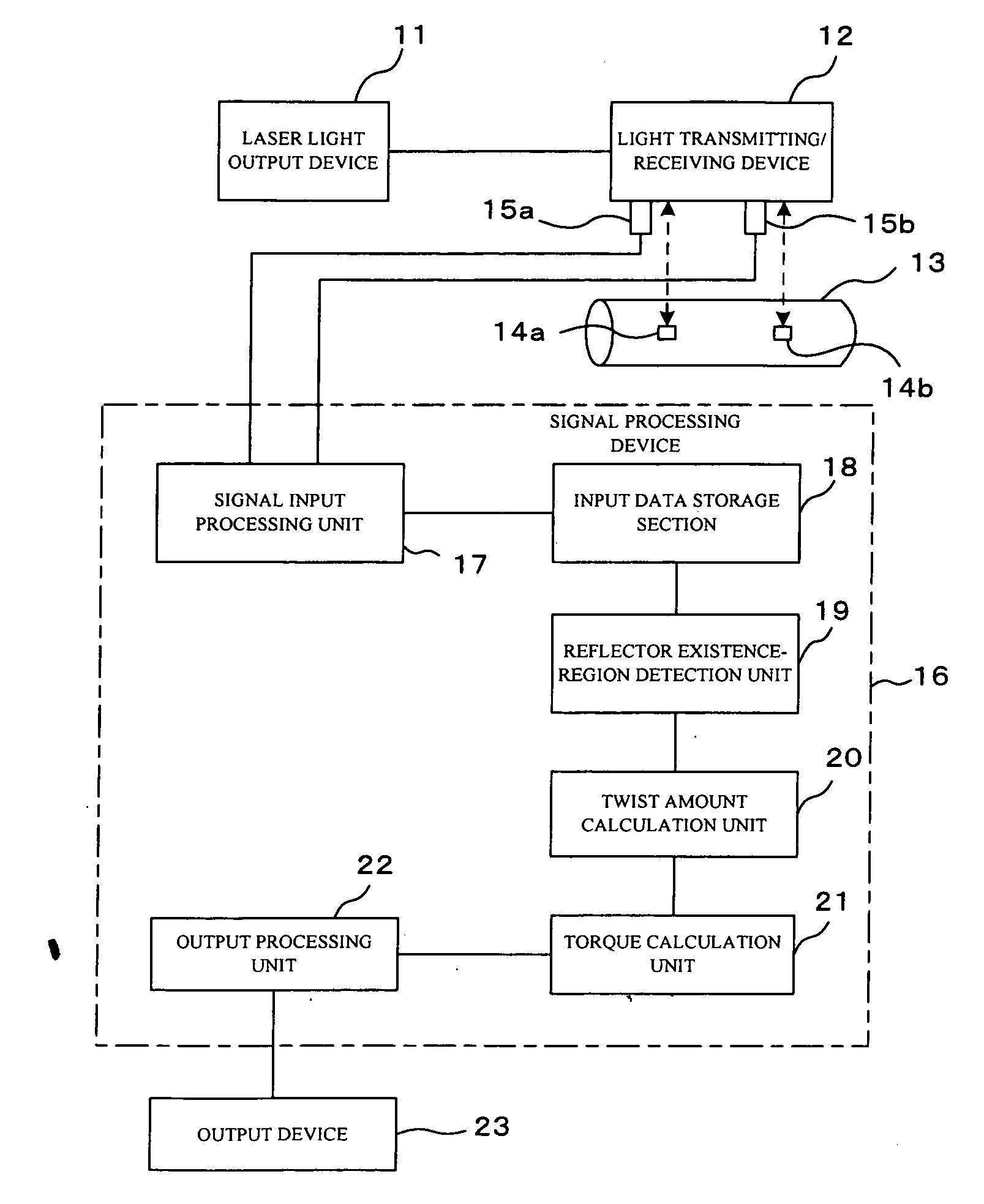
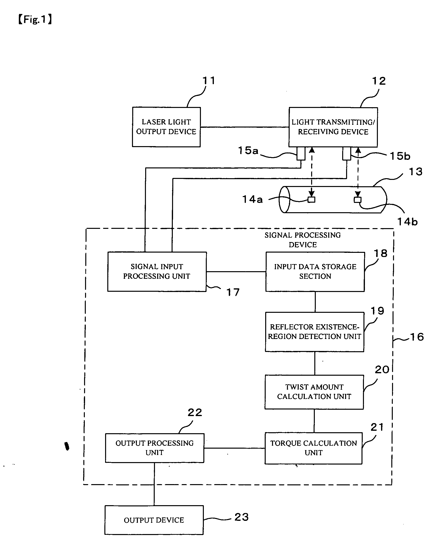
[0023]FIG. 1 is a block configuration diagram of a torque measurement device according to a first embodiment of the present invention. Laser light output from a laser light output device 11 irradiates the surface of a rotating body 13 via a light transmitting / receiving device 12. A pair of reflectors 14a and 14b is provided on the surface of the rotating body 13, having a spacing in the axial direction, and reflects the irradiating laser light from the light transmitting / receiving device 12 in a predetermined reflection pattern. Each of the reflectors 14a and 14b has a reflection pattern which is formed in a bar-code pattern having a portion reflecting the laser light and a portion absorbing the laser light, for example, and generates reflected light according to the reflection pattern when irradiated by the laser light. The reflected light reflected on the surface of the rotating body 13 including the reflectors 14a and 14b is received by the light transmitting / receiving device 12,...

second embodiment

[0047]FIG. 6 is a block configuration diagram of a torque measurement device according to a second embodiment of the present invention. This second embodiment provides an approximate reflector-position detection unit 24 added to the first embodiment shown in FIG. 1 for detecting approximate positions of the pair of reflectors 14a and 14b using the reflected light data of the rotating body 13 stored in the input data storage section 18, and the reflector existence-region detection unit 19 specifies the reflector positions by detecting the existence regions of the pair of reflectors 14a and 14b from the reflected light data in the neighborhoods of the approximate positions of the pair of reflectors 14a and 14b, which are detected by the approximate reflector-position detection unit 24. The same element as that in FIG. 1 is denoted by the same symbol and repeated explanation will be omitted.

[0048]The approximate reflector-position detection unit 24 inputs the reflected light data of th...


PUM


Abstract

[Problems] To provide a torque measurement device capable of more accurately specifying positions of reflectors which are attached to a rotating body, and more accurately obtaining a torque of the rotating body.
[Means for Solving Problems] A pair of reflectors (14a, 14b) is provided on the surface of the rotating body (13) and has a spacing in the axial direction, reflected light data obtained by reflection of reflection patterns in the pair of reflectors (14a, 14b) is input and stored, a point of minimizing AIC is determined for a model of the reflected light data from the rotating body (13), and existence regions of the pair of reflectors (14a, 14b) are detected. Then, a twist amount of the rotating body (13) is calculated from the reflector positions specified by the detected existence regions of the pair of reflectors (14a, 14b), and the torque is calculated from the calculated twist amount of the rotating body.

Description

TECHNICAL FIELD[0001]The present invention relates to a torque measurement device and a torque measurement program, which measure a rotating speed and an axial torque of a rotating body optically in a non-contact mode.BACKGROUND ART[0002]There has been developed an optical torque measurement device for detecting a torque of a drive axis (rotating body) in rotating equipment such as a gas turbine and a steam turbine, for the purpose of identifying a cause of change in a thermal efficiency of a combined-cycle generating plant or a steam turbine plant, for example. This torque measurement device provides a pair of reflectors at different positions on the rotating body in the axial direction thereof, irradiates both of the reflectors with laser light and detects reflected light thereof from both of the reflectors, obtains a rotation period of the rotating body from periodical strong and weak intensities of the reflected light, and detects a torque of the rotating body from a delay time ...

Claims


Application Information

Patent Timeline
IPC IPC(8): G01L3/00G06F19/00
CPCG01L3/12
Inventor UMEZAWA, SHUICHI
Owner THE TOKYO ELECTRIC POWER CO INC
Why Eureka
Try Eureka