
Sabot projectile

Active Publication Date: 2010-01-07
RHEINMETALL WAFFE MUNITION GMBH
View PDF12 Cites 10 Cited by
  • Summary
  • Abstract
  • Description
  • Claims
  • Application Information

AI Technical Summary

Benefits of technology

[0006]The objective of the present invention is to provide a sabot projectile, which is relatively inexpensive to manufacture, has a low weight, and ensures good detachment of the sabot as soon as the sabot projectile has left a corresponding gun barrel after discharge.
[0008]The transverse ribs stiffen the structure when open and support the guide disk on a smaller diameter during acceleration. The ribs can be closed by partitions at least one predetermined distance from the inside wall of the hollow cylinder, so that several cavities are formed, which surround the central opening and extend in the direction of the longitudinal axis of the sabot. Preferably, the partitions, which are adjacent to the projectile body, can join the ends of the transverse ribs that face the projectile body.
[0009]Especially when a light metal is used (for example, an aluminum or magnesium alloy), a guide cage of this type can be manufactured especially inexpensively if it is an extruded profile part that is then subjected to finishing work (for example, the profile is bored) and segmented or even divided in the axial direction. In addition, despite its low weight due to the cavities, the guide cage has sufficient stability and stiffness for the discharge of the corresponding sabot projectile.
[0010]It has been found to be advantageous if the guide cage has four or preferably eight chamber-like cavities arranged with uniform distribution around the circumference, wherein the function of the guide cage is ensured even with one (or two) semicircular cavity (cavities), even without transverse ribs.
[0024]An advantage associated with this solution is that the guide cage becomes inexpensive. Furthermore, it results in very good operation with small amounts of plastic after discharge, for example, in the field. The guide cage is stable with respect to temperature and loading and has a low weight.

Problems solved by technology

One of the disadvantages of this previously known sabot is that the manufacture of the guide cage is relatively expensive.

Method used


Image

  • Sabot projectile
  • Sabot projectile
  • Sabot projectile

Examples


Embodiment Construction

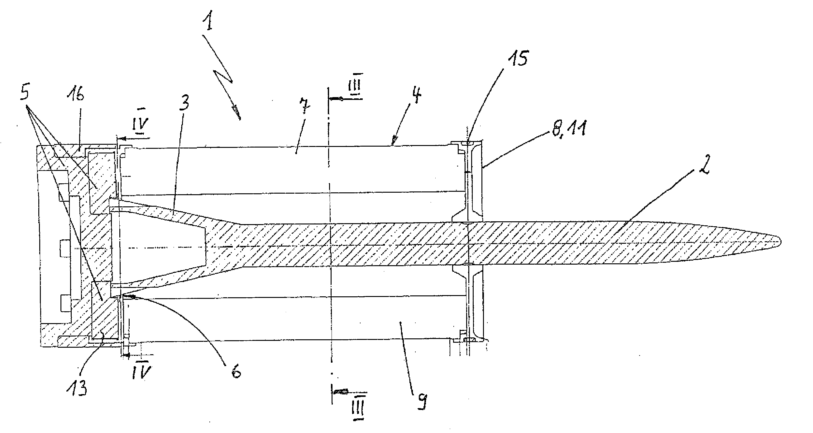
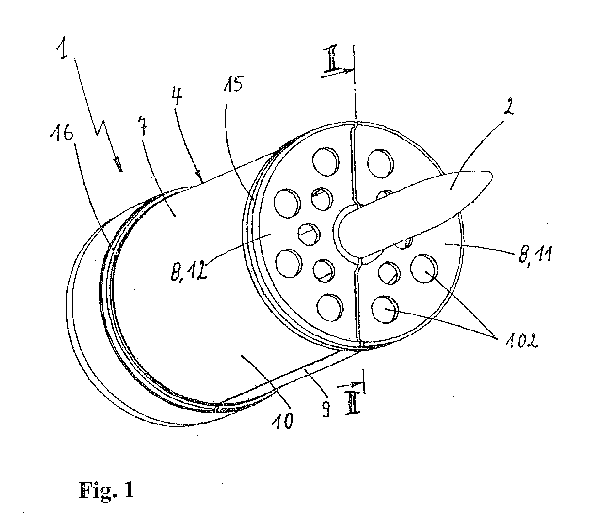
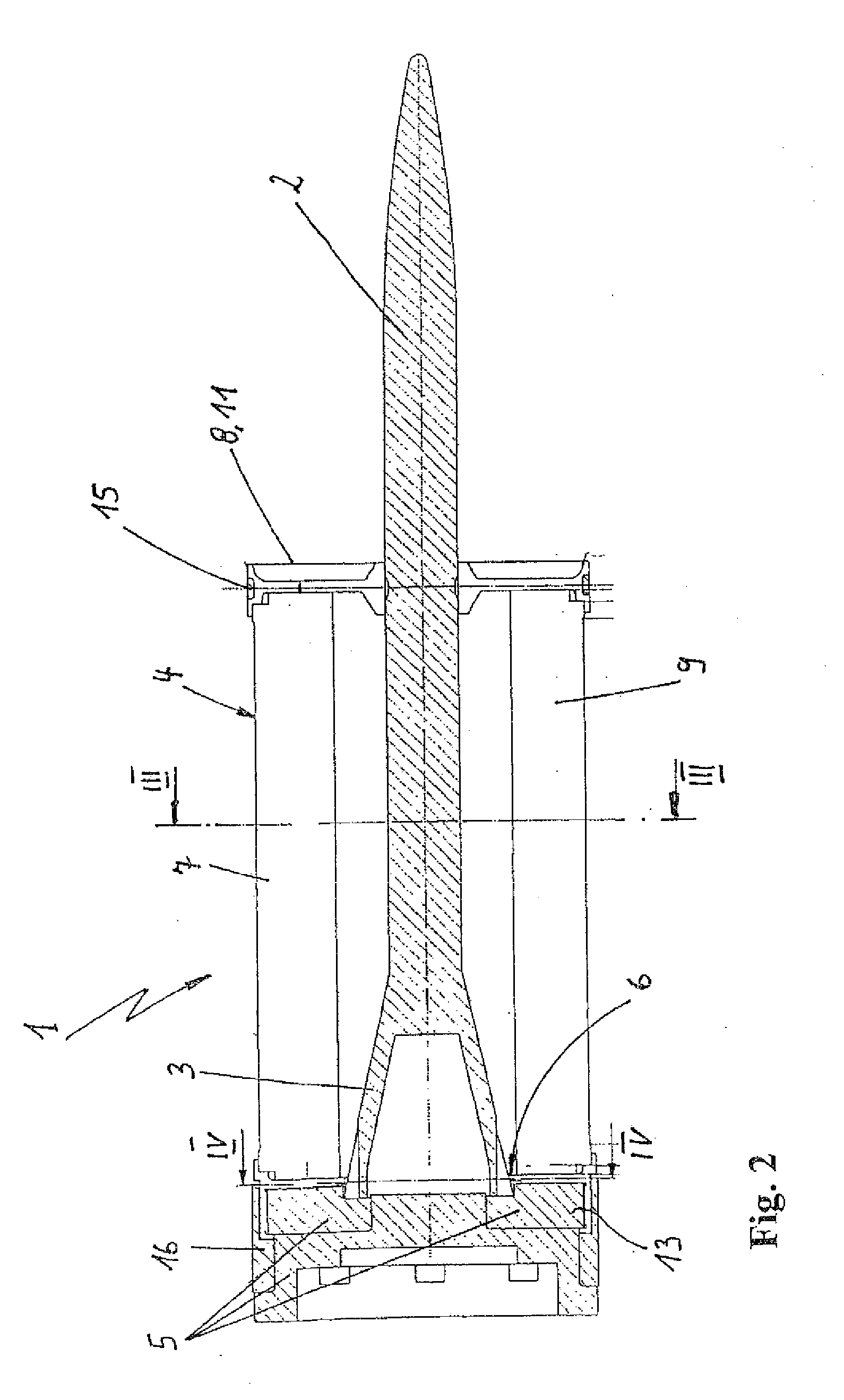
[0036]FIGS. 1 and 2 show a sabot projectile 1, which comprises a subcaliber projectile body 2 with a conical tail stabilizer 3 and a sabot 4.

[0037]The sabot 4 consists essentially of a multisectional propulsion element 5 that acts from the rear on the projectile body 2 (FIG. 2) and is joined with the rear end of the projectile body 2 by a compression joint 6, a cylindrical guide cage 7 connected to the front end of the propulsion element 5, and a support wall 8 with air holes 102, which is located in the front region of the guide cage 7, extends radially inward and supports the projectile body 2.

[0038]The guide cage 7 consists of two segments 9, 10 in the form of half shells made of an aluminum alloy. The support wall 8, on the other hand, consists of two half disks 11, 12, which can also be made of an aluminum alloy. These half disks 11, 12 are joined with the segments 9, 10 of the guide cage 7, for example, by means of adhesive bonding. The same applies to the joining of two segme...


PUM


Abstract

A sabot projectile with a subcaliber projectile body and a sabot, which includes a propulsion element that acts on the rear end of the projectile body and a segmented, essentially cylindrical metal guide cage, which is located at the front end of the propulsion element. The guide cage has a central opening that extends in the axial direction, through which the projectile body is passed. So that the sabot projectile is relatively inexpensive to manufacture, has a low weight, and ensures good detachment of the sabot from the projectile body after discharge, the guide cage is a hollow cylinder, on whose inside wall preferably several radial transverse ribs are arranged, which are spaced some distance apart and extend both in the direction of the longitudinal axis of the sabot and in the direction of the projectile body.

Description

[0001]The present application claims priority from U.S. Provisional Patent Application No. 61 / 199,832 filed Nov. 20, 2008, the entire contents of which are incorporated by reference.BACKGROUND OF THE INVENTION[0002]The invention concerns a sabot projectile with a subcaliber projectile body and a sabot, which comprises a propulsion element that acts on the rear end of the projectile body and a segmented, essentially cylindrical metal guide cage, which is located at the front end of the propulsion element. The guide cage has a central opening that extends in the axial direction, through which the projectile body is passed.[0003]A sabot projectile of this type is disclosed, for example, by DE 43 30 417 C2. It has an essentially hollow cylindrical aluminum guide cage that consists of two segments and that is joined as a single piece with a forward support wall.[0004]One of the disadvantages of this previously known sabot is that the manufacture of the guide cage is relatively expensive....

Claims


Application Information

Patent Timeline
IPC IPC(8): F42B14/06F42B14/08
CPCF42B14/064F42B5/18
Inventor BAUMANN, CHRISTIANFREUDENTHAL, KLAUS-DIETERHEITHMANN, THOMASVAGEDES, MICHAEL
Owner RHEINMETALL WAFFE MUNITION GMBH
Learn More