Component-mounted board production apparatus and position control method for electronic components in component-mounted board production apparatus

a technology of component-mounted boards and production apparatuses, which is applied in the direction of final product manufacturing, soldering apparatus, manufacturing tools, etc., can solve the problems of difficult to ensure the mounting quality of electronic components, the inability to properly control the position of electronic components,

Active Publication Date: 2010-01-07
PANASONIC CORP
View PDF7 Cites 11 Cited by
  • Summary
  • Abstract
  • Description
  • Claims
  • Application Information

AI Technical Summary

Benefits of technology

[0005]However, in a case where, for example, solder paste pieces are printed at positions offset from the board-side electrodes, there is a displacement between a placement position of the electronic component before solder reflowing and a mounting position of the electronic component after the solder reflowing due to the self alignment effect of the molten solder. Therefore, the criterion by which the placement position of the electronic component before reflowing or the mounting position of the electronic component after reflowing is inspected is not clarified in the conventional electronic component mounting including Japanese patent publication No. 2002-84097 or the like. For example, under a condition that a board-side electrode position is adopted as the inspection criterion, there may be a case where an electronic component placed so as to be consistent with the print position of solder printed with an offset from the board-side electrode position is decided to have been offset in its placement position as an inspection result. Under another condition that the print position of solder that has been offset in its print position is adopted as an inspection criterion, there may be a case where an electronic component is decided to have been offset in its mounting position due to a placement of its mounting position caused by the self alignment effect of molten solder, as an inspection result. In such cases, position control of electronic components could not properly be fulfilled, making it difficult in some cases to ensure mounting quality of the electronic components.
[0006]Accordingly, an object of the present invention, lying in solving the above-described issues, is to provide a component-mounted board production apparatus prepared for displacements of electronic components due to the self alignment effect of molten solder as well as a position control method for electronic components in the component-mounted board production apparatus.

Problems solved by technology

However, in a case where, for example, solder paste pieces are printed at positions offset from the board-side electrodes, there is a displacement between a placement position of the electronic component before solder reflowing and a mounting position of the electronic component after the solder reflowing due to the self alignment effect of the molten solder.
In such cases, position control of electronic components could not properly be fulfilled, making it difficult in some cases to ensure mounting quality of the electronic components.

Method used


Image

  • Component-mounted board production apparatus and position control method for electronic components in component-mounted board production apparatus
  • Component-mounted board production apparatus and position control method for electronic components in component-mounted board production apparatus
  • Component-mounted board production apparatus and position control method for electronic components in component-mounted board production apparatus

Examples


Embodiment Construction

[0040]Before the description of the present invention proceeds, it is to be noted that like parts are designated by like reference numerals throughout the accompanying drawings.

[0041]Hereinbelow, an embodiment of the present invention will be described in detail with reference to the accompanying drawings.

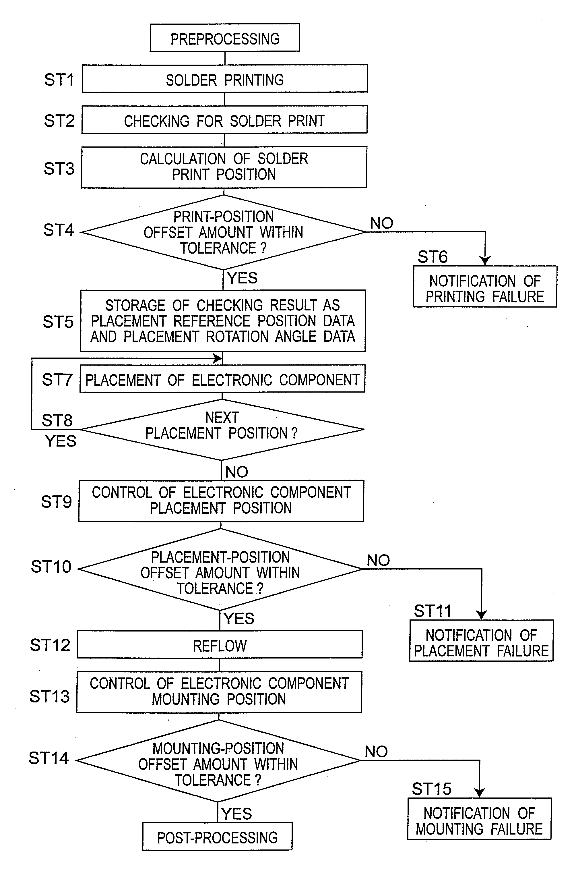
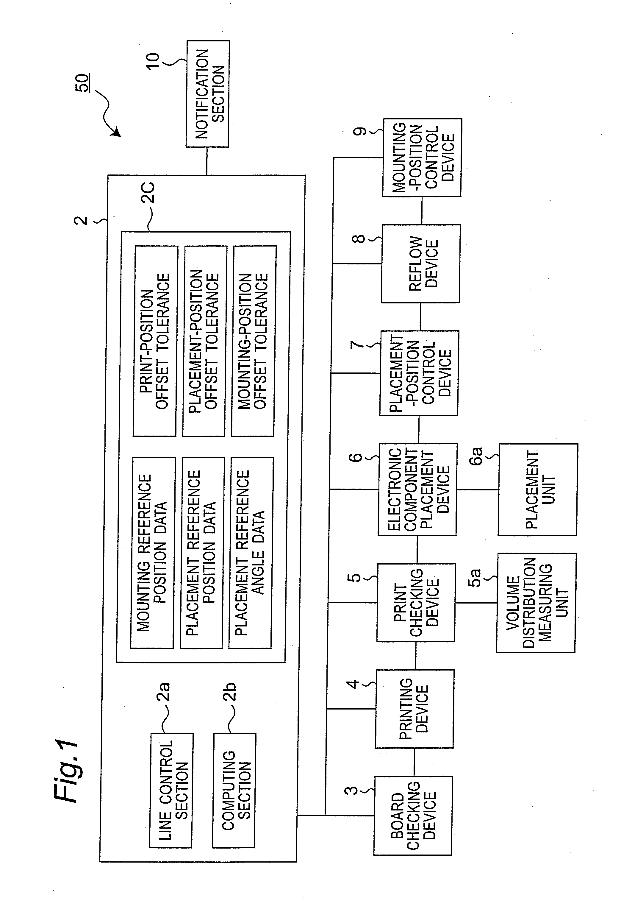
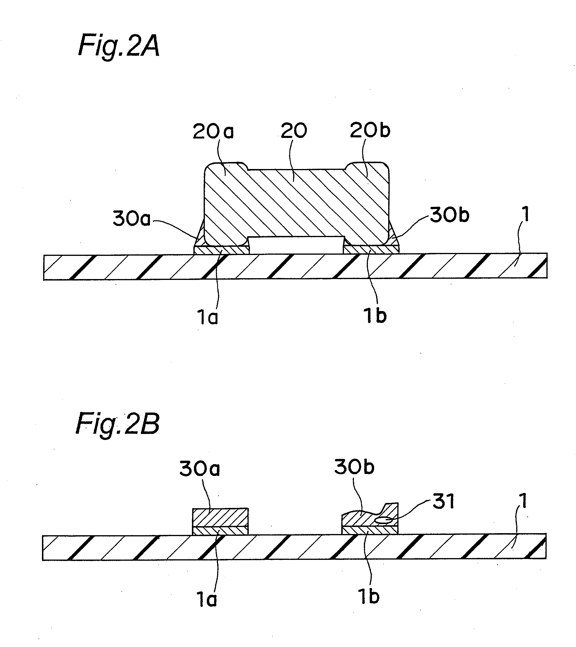
[0042]FIG. 1 is a configuration diagram of an electronic component mounting line which is an example of the component-mounted board production apparatus according to an embodiment of the present invention. FIG. 2A is a side view showing a state that an electronic component is mounted on a board in the electronic component mounting line of the embodiment. FIG. 2B is a side view showing a state that solder paste pieces as an example of solder are printed on board-side electrodes. FIG. 3A is a plan view showing a state that solder paste pieces are printed in normal positions on the board-side electrodes. FIG. 3B is a plan view showing a state that solder paste pieces are printed in of...


PUM

PropertyMeasurementUnit
volume distributionaaaaaaaaaa
volumeaaaaaaaaaa
volume distribution measuringaaaaaaaaaa

Abstract

The electronic component mounting line includes computing unit for calculating a print position of solder paste printed on board-side electrodes, electronic component placement device for placing an electronic component onto the board-side electrodes by referencing the print position of the solder paste, placement position control device for controlling the placement position of the electronic component by referencing the print position of the solder paste, bonding device for melting the solder paste to bond the electronic component and the board-side electrodes to each other, and mounting-position control device for controlling the mounting position of the electronic component by referencing the board-side electrode position. In this configuration, position control responsive to a displacement of the electronic component by the self alignment effect exerted by the molten solder paste is fulfilled.

Description

TECHNICAL FIELD[0001]The present invention relates to a component-mounted board production apparatus for mounting electronic components onto a board on which solder is placed on its board-side electrodes, as well as to a position control method for electronic components in the component-mounted board production apparatus.BACKGROUND ART[0002]For mounting of electronic components onto a board such as a printed circuit board having electrodes formed on its top surface, a widely practiced method is that with solder paste preliminarily printed on the board-side electrodes and with component-side electrodes placed on the solder paste pieces, solder reflowing is performed so that the component-side electrodes well get wet with the molten solder to fulfill the bonding. The board-side electrodes and the component-side electrodes need to be accurately bonded to each other, respectively, with a view to ensuring the mounting quality. However, there are some cases where the solder paste printed ...

Claims


Application Information

Patent Timeline
Patent Type & Authority Applications(United States)
IPC IPC(8): B23K20/00B23Q16/00B23K20/26
CPCH05K1/0269H05K3/341H05K3/3484H05K13/0408H05K13/0465Y10T29/49149H05K2201/10636H05K2203/163Y10T29/49124Y10T29/49144H05K13/08H05K13/0817H05K3/3485Y02P70/50B23K1/00
Inventor NAGAI, DAISUKE
Owner PANASONIC CORP
Why Eureka
Try Eureka