
Mounting apparatus and mounting method

a technology of mounting apparatus and mounting method, which is applied in the direction of presses, semiconductor/solid-state device details, semiconductor devices, etc., can solve the problems of low mounting quality and exact mounting, and achieve the effect of reducing the dislocation of semiconductor chips

Active Publication Date: 2014-06-05
SAMSUNG ELECTRONICS CO LTD
View PDF7 Cites 1 Cited by
  • Summary
  • Abstract
  • Description
  • Claims
  • Application Information

AI Technical Summary

Benefits of technology

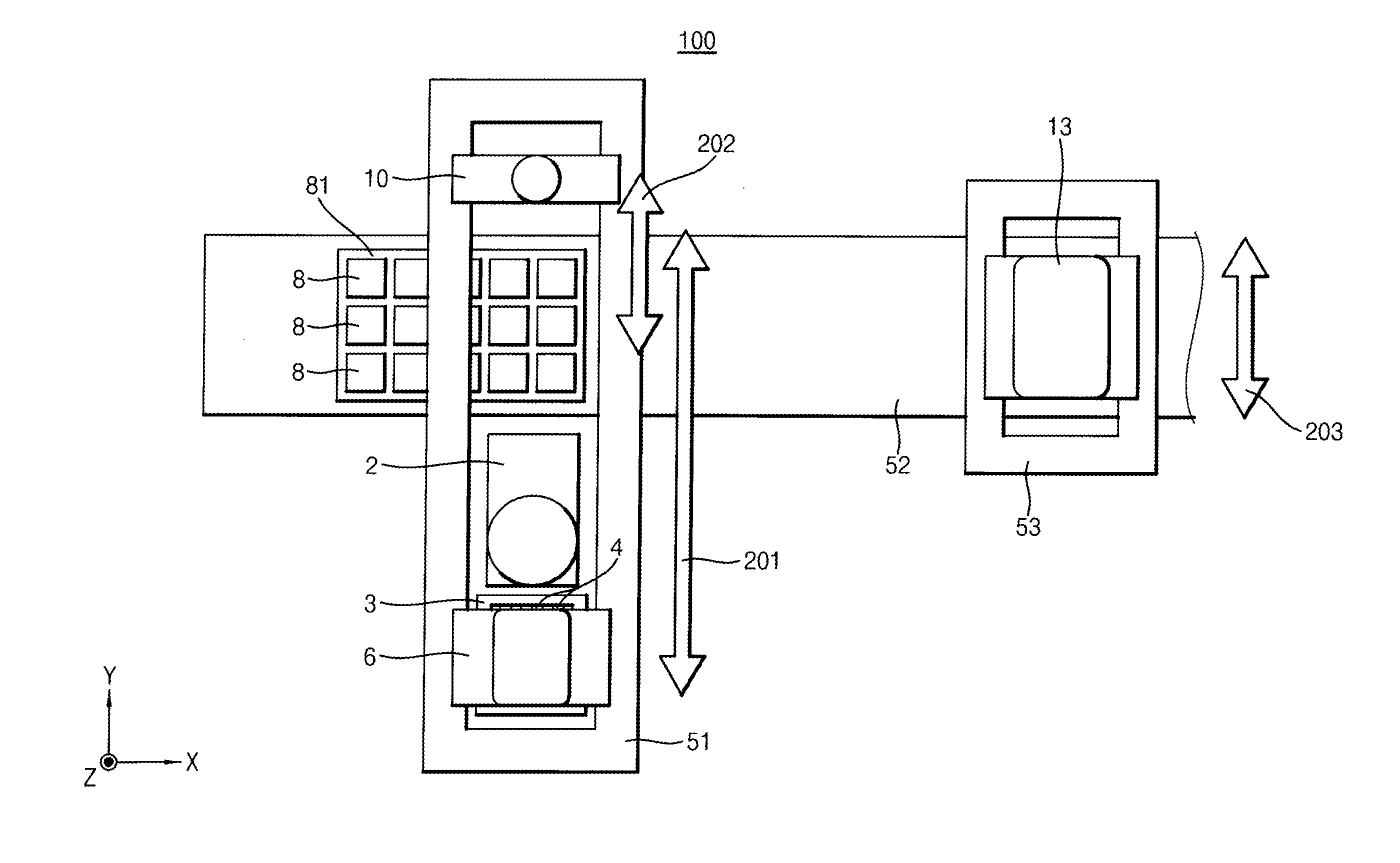
The patent text describes a technique for improving the quality of mounting semiconductor chips using a flip chip connection. The technique involves dividing the thermal pressing into a preliminary bonding and a main bonding, with the main bonding being done when the chip is re-heated. However, this can cause the chip to become dislodged, affecting the mounting quality. The patent proposes a mounting apparatus and method that reduces this dislocation by adsorbing the chips onto a substrate before heating them up for the main bonding. This results in a more exact and quality mounting of multiple semiconductor chips simultaneously.

Problems solved by technology

Additionally, in order to absorb a height deviation of the pressing blocks, each pressing block may be supported so as to freely move up and down, and may be burdened by pressing an air press through an elastic layer.
That is, when a chip is re-heated for the main bonding, the position of the chip may be dislocated, which may lower the quality of mounting, e.g., the exactness of the mounting density of chips.

Method used


Image

  • Mounting apparatus and mounting method
  • Mounting apparatus and mounting method
  • Mounting apparatus and mounting method

Examples


Embodiment Construction

[0020]Various example embodiments will be described more fully hereinafter with reference to the accompanying drawings, in which some example embodiments are shown. The present inventive concept may, however, be embodied in many different forms and should not be construed as limited to the example embodiments set forth herein. Rather, these example embodiments are provided so that this description will be thorough and complete, and will fully convey the scope of the present inventive concept to those skilled in the art. In the drawings, the sizes and relative sizes of layers and regions may be exaggerated for clarity.

[0021]It will be understood that when an element or layer is referred to as being “on,”“connected to” or “coupled to” another element or layer, it can be directly on, connected or coupled to the other element or layer or intervening elements or layers may be present. In contrast, when an element is referred to as being “directly on,”“directly connected to” or “directly ...


PUM

PropertyMeasurementUnit
Timeaaaaaaaaaa

Abstract

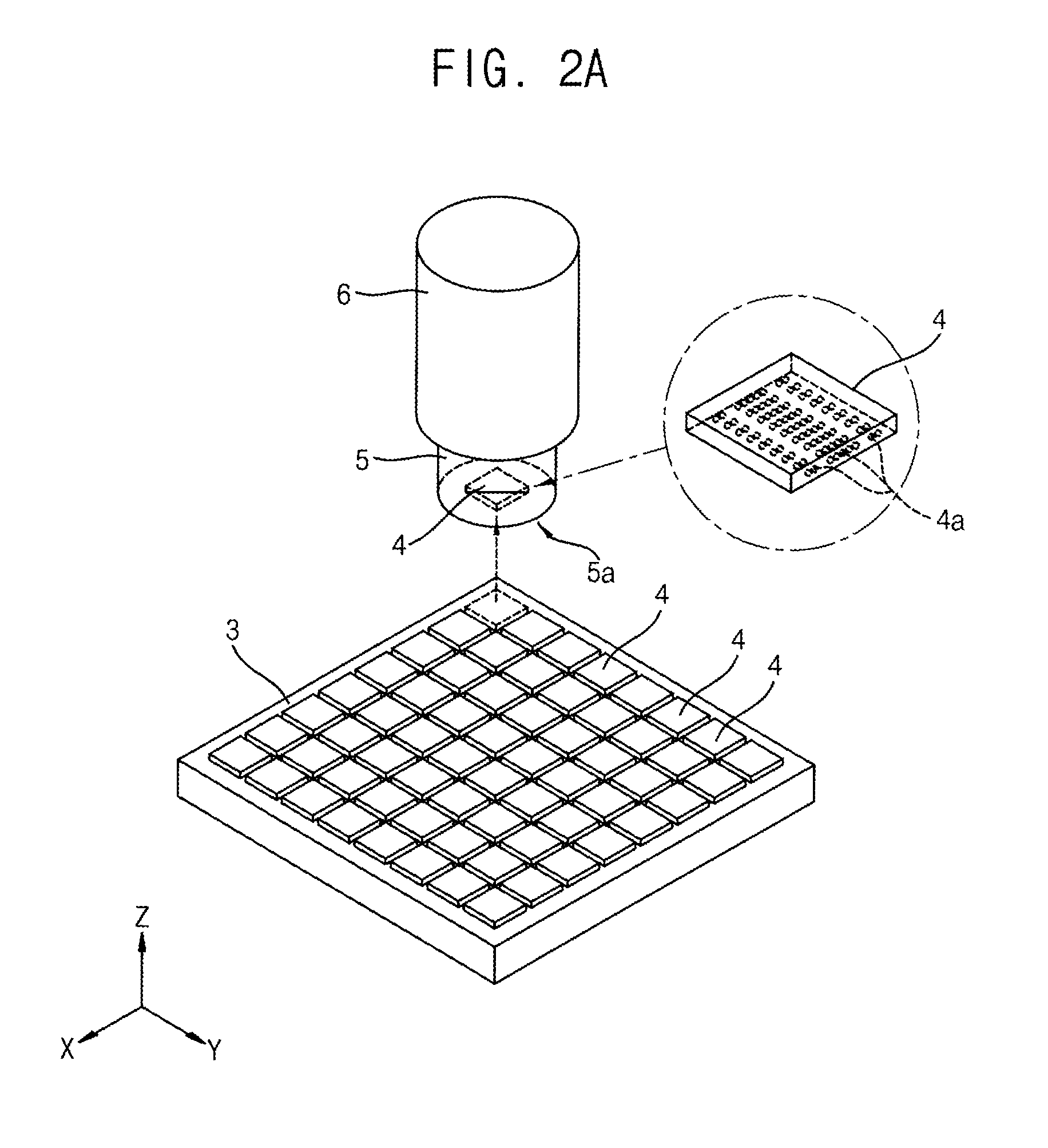
In one embodiment the mounting apparatus mounts an upper chip on a lower chip, and thermally presses the upper chip with the lower chip. The mounting apparatus includes a first movement part for mounting the upper chip on the lower chip and preliminarily bonding by thermal pressing, and a second movement part for mainly bonding the plurality of upper chips preliminarily bonded with the plurality of lower chips for a longer time. The second movement part thermally presses the upper chips preliminarily bonded on the lower chip in a state that the upper chips are adsorbed on an adsorption surface parallel to a loading surface of the lower chip on which the upper chips are loaded.

Description

CROSS-REFERENCE TO RELATED APPLICATION[0001]This application claims priority under 35 U.S.C. §119 to Japanese Patent Application No. 2012-265493, filed on Dec. 4, 2012 in the Japanese Intellectual Property Office, the contents of which are herein incorporated by reference in their entirety.BACKGROUND[0002]1. Field[0003]Example embodiments relate to an apparatus for mounting a semiconductor chip on a substrate and a method for mounting using the same.[0004]2. Description of the Related Art[0005]A flip chip connection that may be used for connecting semiconductor chips in a three-dimensional mounting or for mounting a semiconductor chip on a substrate may use a plurality of conductive bumps arranged in an array and connect chips and chips or chips and a substrate electrically and mechanically. As a method of mounting a plurality of chips on a substrate using a flip chip connection, a thermal pressing process may be divided into two steps so as to increase the productivity (patent docu...

Claims


Application Information

Patent Timeline
IPC IPC(8): H01L23/00H01L21/67
CPCH01L21/67144H01L21/681H01L24/75H01L24/81H01L24/97H01L25/0652H01L2224/16145H01L2224/16225H01L2224/32145H01L2224/32225H01L2224/73204H01L2224/73253H01L2224/75252H01L2224/75753H01L2224/7598H01L2224/81123H01L2224/81203H01L2224/81815H01L2225/06568H01L2924/15311H01L2924/00012H01L2924/00H01L21/50
Inventor YOSHIAKI, YUKIMORIMASATO, KAJINAMISHINJI, UEYAMA
Owner SAMSUNG ELECTRONICS CO LTD
Learn More