A placement machine

A technology of placement machine and body, applied in the orientation of circuit board tools, printed circuits, electrical components, etc., can solve problems such as hindering the precise positioning of component placement positions, component position deviation, substrate vibration, etc., to facilitate transportation, slow down Vibration and damage reduction effect

Active Publication Date: 2021-06-01
江苏盐湖电子科技有限公司
View PDF0 Cites 1 Cited by
  • Summary
  • Abstract
  • Description
  • Claims
  • Application Information

AI Technical Summary

Problems solved by technology

[0002] SMD is a circuit assembly technology that mounts non-lead or short-lead surface mount components on the surface of a printed circuit board or other substrates, and solders and assembles them by reflow soldering or dip soldering. During the placement process, since the component is pressed on the substrate from the z-axis direction under the action of a certain amount of placement force and is stuck by viscous media such as solder paste and adhesive or flux, the suction of the placement head The nozzle will press the substrate down; and now the placement machine is more and more efficient, and the assembly speed of the suction nozzle used to pick up the components to be mounted on the placement head has also become very fast, so that the substrate will also Vibration is generated under the impact of each assembly; on the one hand, the frequent vibration of the substrate will have an adverse effect on the components to be mounted, such as some sensitive components may be damaged due to the rebound of the substrate, on the other hand, it will also hinder the placement of components The precise positioning of the mounting position; in addition, the vibration or shaking of the substrate may cause the components that have been positioned on the substrate to shift or even slip off the substrate during the mounting process

Method used


Image

  • A placement machine
  • A placement machine
  • A placement machine

Examples


Embodiment Construction

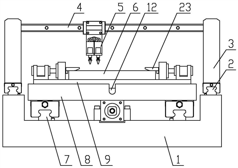
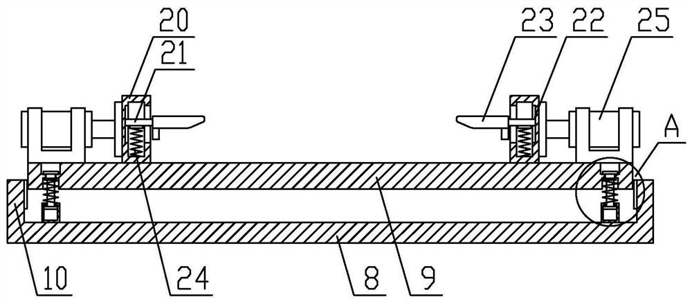
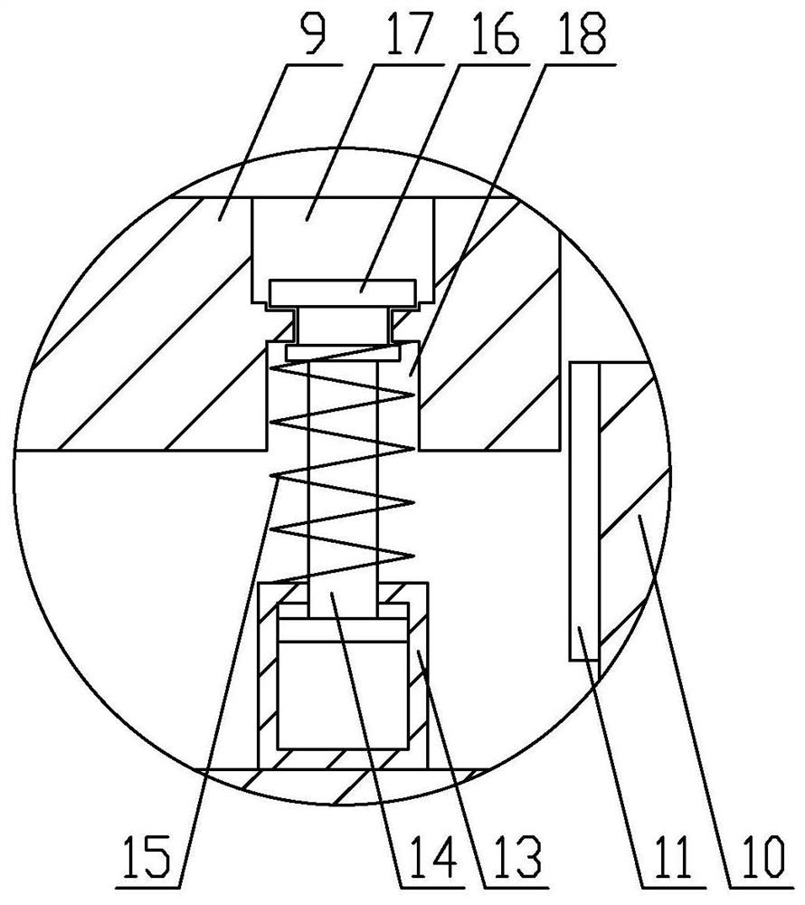
[0018] The following will clearly and completely describe the technical solutions in the embodiments of the present invention with reference to the accompanying drawings in the embodiments of the present invention. Obviously, the described embodiments are only some, not all, embodiments of the present invention. Based on the embodiments of the present invention, all other embodiments obtained by persons of ordinary skill in the art without making creative efforts belong to the protection scope of the present invention.

[0019] In the description of the present invention, it should be understood that the orientations or positional relationships indicated by "front", "rear", "left", "right", "upper" and "lower" in terms are based on those shown in the accompanying drawings. Orientation or positional relationship is only for the convenience of describing the present invention and simplifying the description, and does not indicate or imply that the referred device or element must ...


PUM


Abstract

The invention provides a placement machine, comprising a placement machine body, first guide rails are provided on both sides of the placement machine body, moving columns are slidably installed on the two first guide rails, and a moving column is fixed between the two moving columns. The second guide rail is slidingly connected with the mounting head; the conveying slide rail is arranged under the mounting head, and the conveying platform is slidably installed on the conveying slide rail, and the carrying platform is detachably connected to the conveying platform through a shock absorbing mechanism; The shock mechanism includes a cylinder, a push rod and a damping spring. The upper end of the push rod is provided with a block; the bearing table is provided with a first installation groove and a second installation groove matching the shape of the upper end of the push rod. The clamping block passes through the second installation groove and snaps into the first installation groove; the two sides of the carrying platform are provided with a fixing mechanism, and the fixing mechanism includes a fixing seat, a pull plate, a fixing plate and a tension spring; Shock, which effectively slows down the vibration generated during the mounting process, reduces the damage caused by the vibration, and improves the mounting quality.

Description

technical field [0001] The invention relates to the field of circuit board processing, in particular to a placement machine. Background technique [0002] SMD is a circuit assembly technology that mounts non-lead or short-lead surface mount components on the surface of a printed circuit board or other substrates, and solders and assembles them by reflow soldering or dip soldering. During the placement process, since the component is pressed on the substrate from the z-axis direction under the action of a certain amount of placement force and is stuck by viscous media such as solder paste and adhesive or flux, the suction of the placement head The nozzle will press the substrate down; and now the placement machine is more and more efficient, and the assembly speed of the suction nozzle used to pick up the components to be mounted on the placement head has also become very fast, so that the substrate will also Vibration is generated under the impact of each assembly; on the o...

Claims


Application Information

Patent Timeline
Patent Type & Authority Patents(China)
IPC IPC(8): H05K3/00H05K3/30
CPCH05K3/0008H05K3/30
Inventor 夏建国
Owner 江苏盐湖电子科技有限公司
Why Eureka
Try Eureka