
Fastener Assembly with Cyclone Cooling

a fastener and cyclone cooling technology, applied in the direction of screw, liquid fuel engine, lighting and heating apparatus, etc., can solve the problems of reducing the service life or failure of the fastener, the fastener begins to weaken and loose pre-, and the properties begin to decrease exponentially

Inactive Publication Date: 2010-01-07
SIEMENS ENERGY INC
View PDF14 Cites 11 Cited by
  • Summary
  • Abstract
  • Description
  • Claims
  • Application Information

AI Technical Summary

Benefits of technology

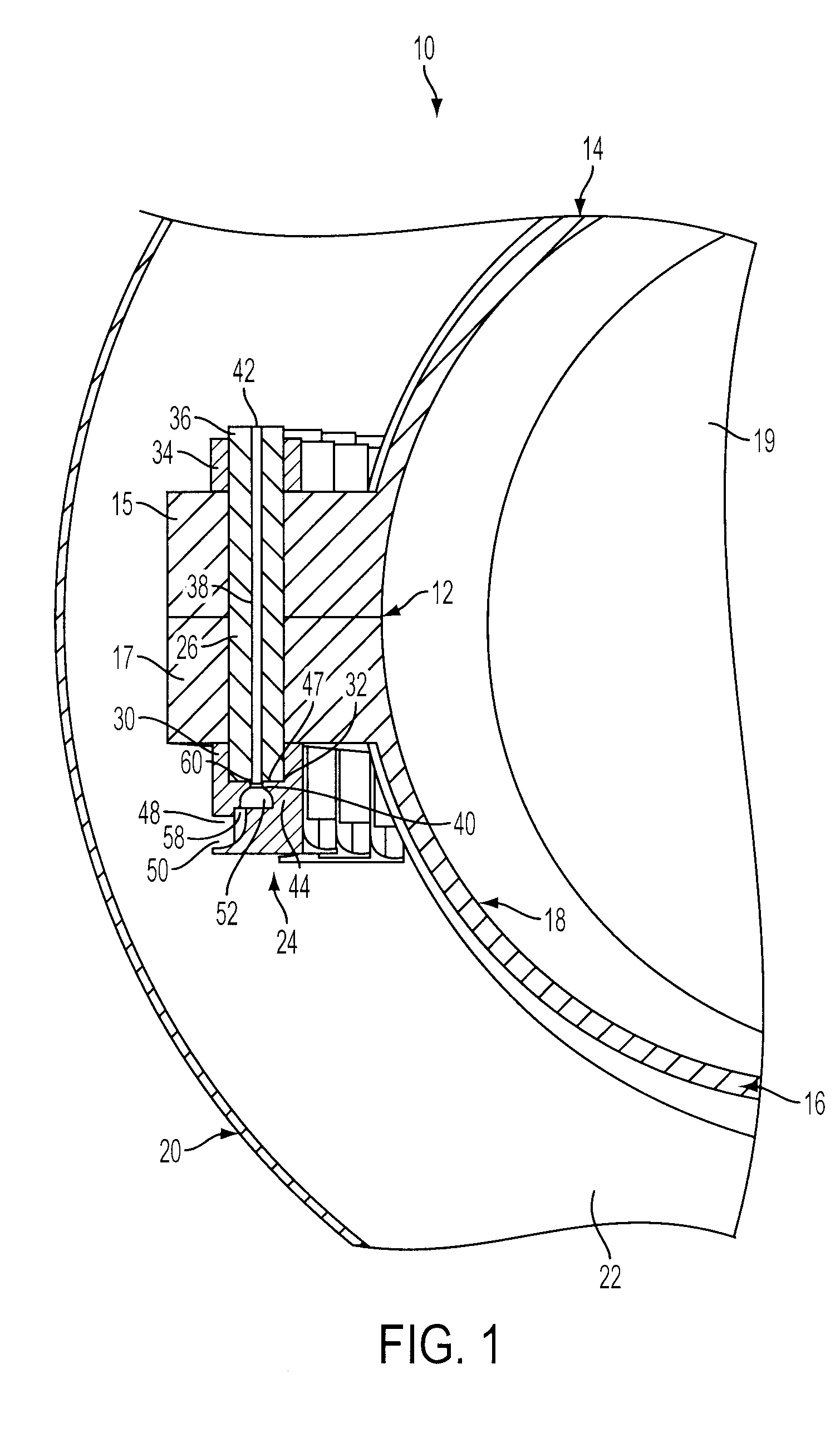
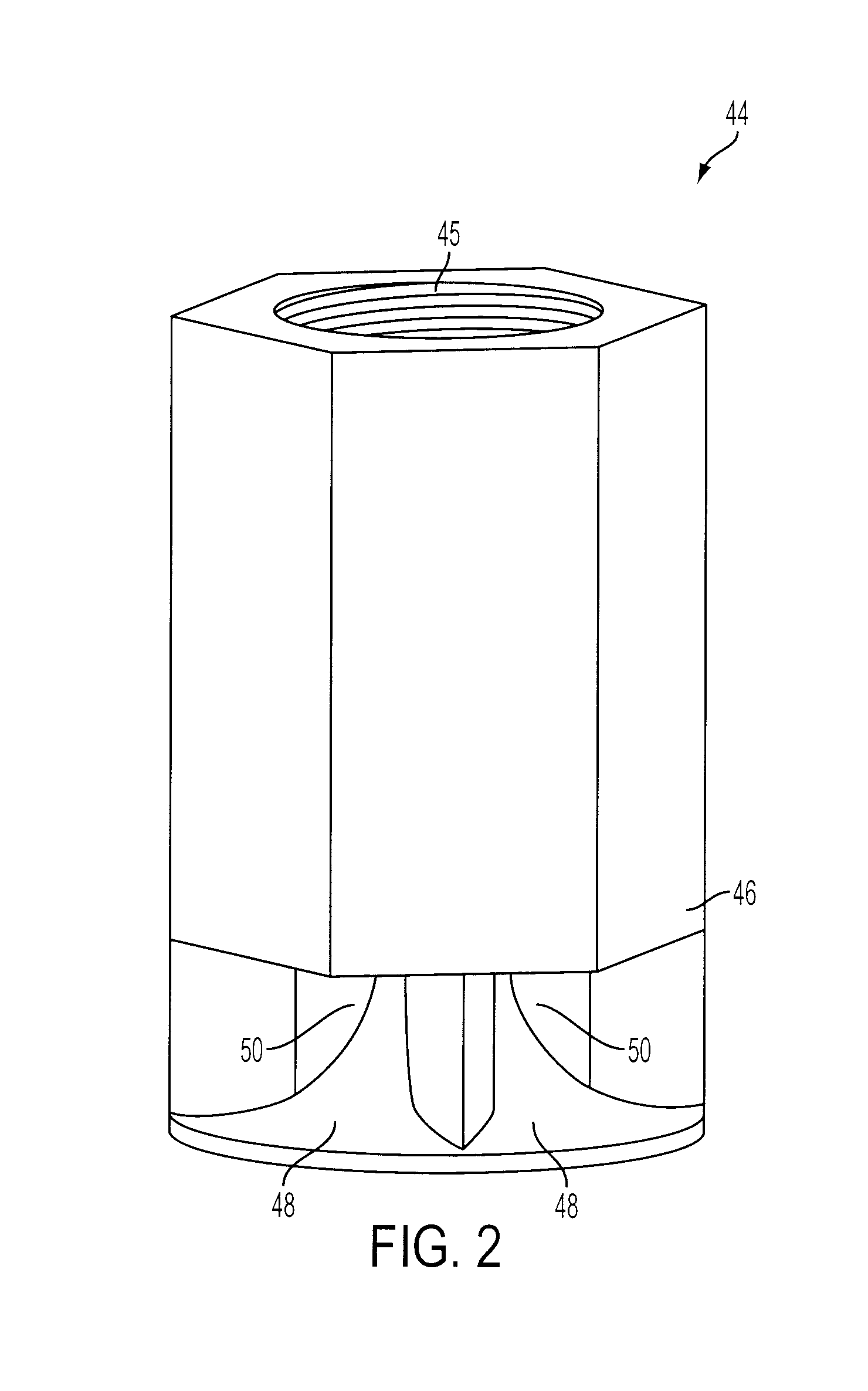
[0006]The coolant collector may further comprise a nozzle chamber disposed between the contoured passage and the coolant passage in the fastener. The nozzle chamber may be configured to receive the cooling fluid from the contoured passage and to accelerate the cooling fluid flowing through the nozzle chamber such that the heat transfer rate between the cooling fluid and at least one of the coolant collector and the fastener is further increased.
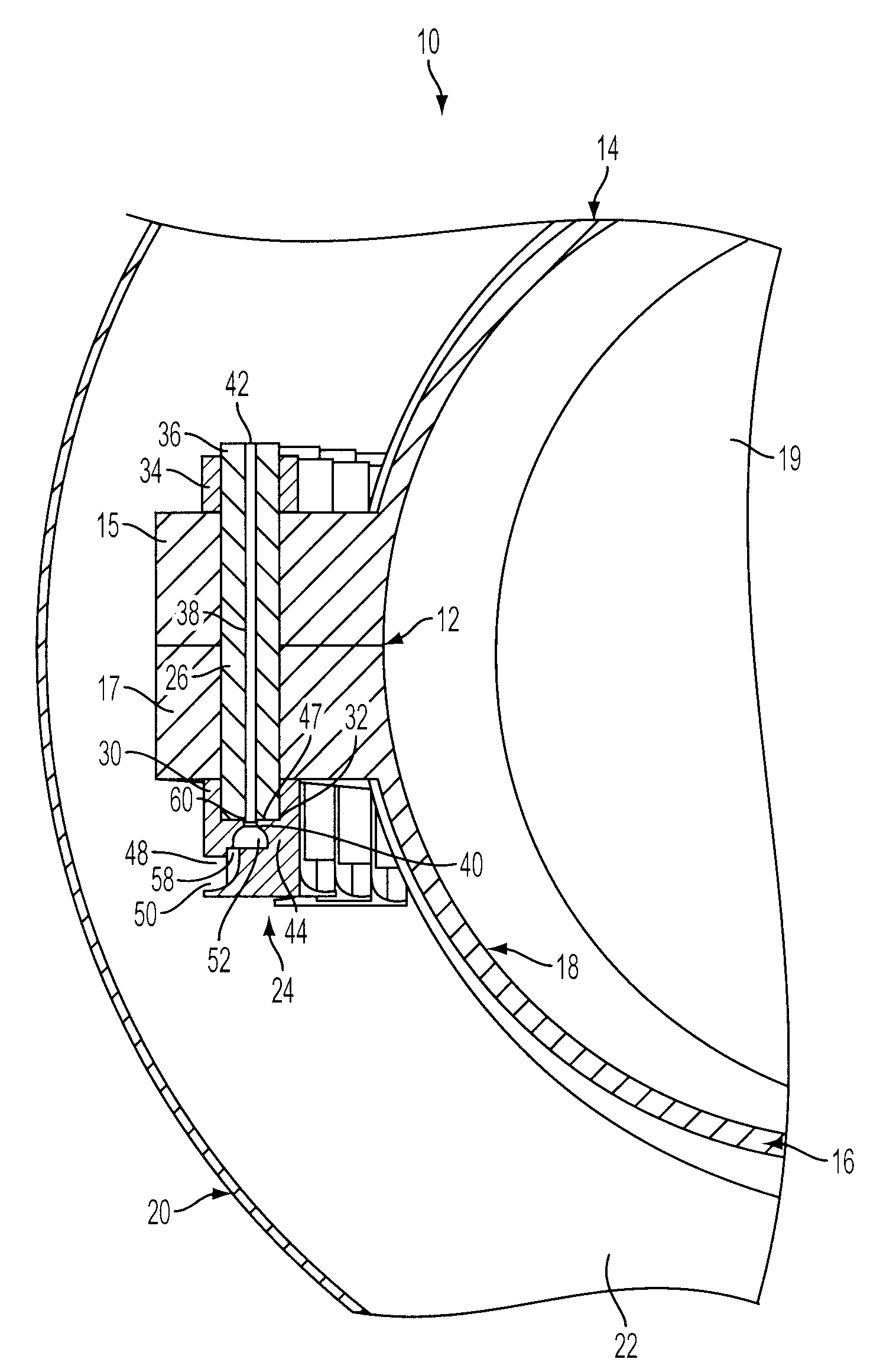
[0007]In accordance with a second aspect of the present invention, a turbine joint including an inner casing and an outer casing defining a steam passage therebetween is provided. The turbine joint may comprise an inner casing upper flange, an inner casing lower flange and a fluid cooled fastener assembly for joining the inner casing upper flange to the inner casing lower flange. The fluid cooled fastener assembly may comprise a fastener having a coolant passage extending axially through the fastener from a collector end to a discharge end and a coolant collector coupled to the collector end of the fastener. The coolant collector may comprise an exterior surface having a collector inlet therein. The collector inlet may be configured to capture a portion of a cooling fluid flowing past the collector inlet. The coolant collector may further comprise a contoured passage in communication with the collector inlet. The contoured passage may be configured to accelerate the cooling fluid flowing into the collector inlet such that a heat transfer rate between the cooling fluid and at least one of the coolant collector and the fastener is increased. The contoured passage may be further configured to direct the cooling fluid into the coolant passage in the fastener. As the cooling fluid flows through the coolant passage in the fastener from the collector end to the discharge end it removes heat from at least one of the coolant collector and the fastener.

Problems solved by technology

However, some applications, such as joints in steam or gas turbines may expose the fastener assemblies to temperatures that exceed the fastener material's maximum allowable temperature, resulting in a reduced service life or failure of the fastener.
Continued exposure to these high temperatures may cause the fasteners to weaken and loose pre-stress.
As the fasteners enter the creep range, the material properties begin to decrease exponentially leading to failure of the fastener.
The effectiveness of such methods is limited by the heat transfer rate between the fastener and the cooling fluid.

Method used


Image

  • Fastener Assembly with Cyclone Cooling
  • Fastener Assembly with Cyclone Cooling
  • Fastener Assembly with Cyclone Cooling

Examples


Embodiment Construction

[0014]In the following detailed description of the preferred embodiments, reference is made to the accompanying drawings that form a part hereof and in which is shown by way of illustration, and not by way of limitation, specific preferred embodiments in which the invention may be practiced. It is to be understood that other embodiments may be utilized and that changes may be made without departing from the spirit and scope of the present invention.

[0015]The present invention concerns a fluid cooled fastener assembly for use in a high temperature application such as a steam or gas turbine. The fastener assembly may comprise a threaded fastener, for example, a bolt or stud and a threaded nut. A coolant collector, which may be integral with a bolt head or the nut collects a portion of a cooling fluid flowing past the coolant collector and directs it into a contoured passage within the coolant collector. The cooling fluid is accelerated within the contoured passage such that a heat tra...


PUM


Abstract

A fluid cooled fastener assembly for use in a high temperature environment and a method of fluid cooling a fastener assembly are provided. The fastener has a coolant passage extending axially through the fastener and a coolant collector coupled to an end of the fastener. The coolant collector includes a collector opening configured to capture a portion of a cooling fluid flowing past the coolant collector and a contoured passage in communication with the collector opening and the passage in the fastener. The contoured passage is configured to accelerate the cooling fluid captured by the coolant collector and to direct it into the coolant passage in the fastener.

Description

FIELD OF THE INVENTION[0001]The present invention relates to a fluid cooled fastener assembly and a method of fluid cooling a fastener assembly, and more particularly, a fastener assembly having a collector for collecting a cooling fluid and directing the cooling fluid into an internal passage within the fastener.BACKGROUND OF THE INVENTION[0002]Fasteners, such as nut and bolt assemblies, are used in a wide variety of applications. The use of such assemblies has achieved wide acceptance due to their high reliability and relatively low cost as compared to other fastening means. However, some applications, such as joints in steam or gas turbines may expose the fastener assemblies to temperatures that exceed the fastener material's maximum allowable temperature, resulting in a reduced service life or failure of the fastener.[0003]As the demand for higher efficiency turbines increases, the turbines are operated at higher temperatures exposing fasteners used within the turbines to higher...

Claims


Application Information

Patent Timeline
Patent Type & Authority Applications(United States)
IPC IPC(8): F01D25/12F04D29/58F04D27/00F24H9/00
CPCF01D25/12F01D25/243F01D25/265F04D29/584F04D29/624Y10T403/25F04D29/646F16B33/00F05D2260/2212F05D2240/127F04D29/644
Inventor PANG, MICHAEL K.
Owner SIEMENS ENERGY INC
Learn More