Inlet air heating system for a gas turbine engine

a gas turbine engine and heating system technology, applied in the direction of machines/engines, non-positive displacement fluid engines, gas turbine plants, etc., can solve the problems of increasing the temperature of the inlet air, reducing the power provided by reducing the power supply so as to reduce the power of the gas turbine engine without engine efficiency loss

Inactive Publication Date: 2010-01-07
PW POWER SYST LLC
View PDF22 Cites 86 Cited by
  • Summary
  • Abstract
  • Description
  • Claims
  • Application Information

AI Technical Summary

Benefits of technology

[0005]A gas turbine engine has an inlet for delivering air into a compressor section. The compressor section is connected to feed air into a combustion section, where the air mixes with fuel and combusts. The combustion section is connected to turbine rotors such that products of combustion can pass over the turbine rotors to drive the turbine rotors. An exhaust communicates with the turbine sections to receive the products of combustion. A bleed tap communicates the exhaust to the inlet. A control controls the amount of exhaust gasses tapped into the inlet to achieve desired operating conditions without a loss in engine efficiency. Also, an inventive method and a system for reducing the power from a gas turbine engine are claimed.

Problems solved by technology

This heat increases inlet air temperature and reduces the power provided by the gas turbine engine.
The use of the bleed air reduces the power in that as the inlet temperature increases, the provided power decreases.
Unfortunately, bleeding off compressor discharge air reduces engine efficiency.

Method used


Image

  • Inlet air heating system for a gas turbine engine
  • Inlet air heating system for a gas turbine engine

Examples


Embodiment Construction

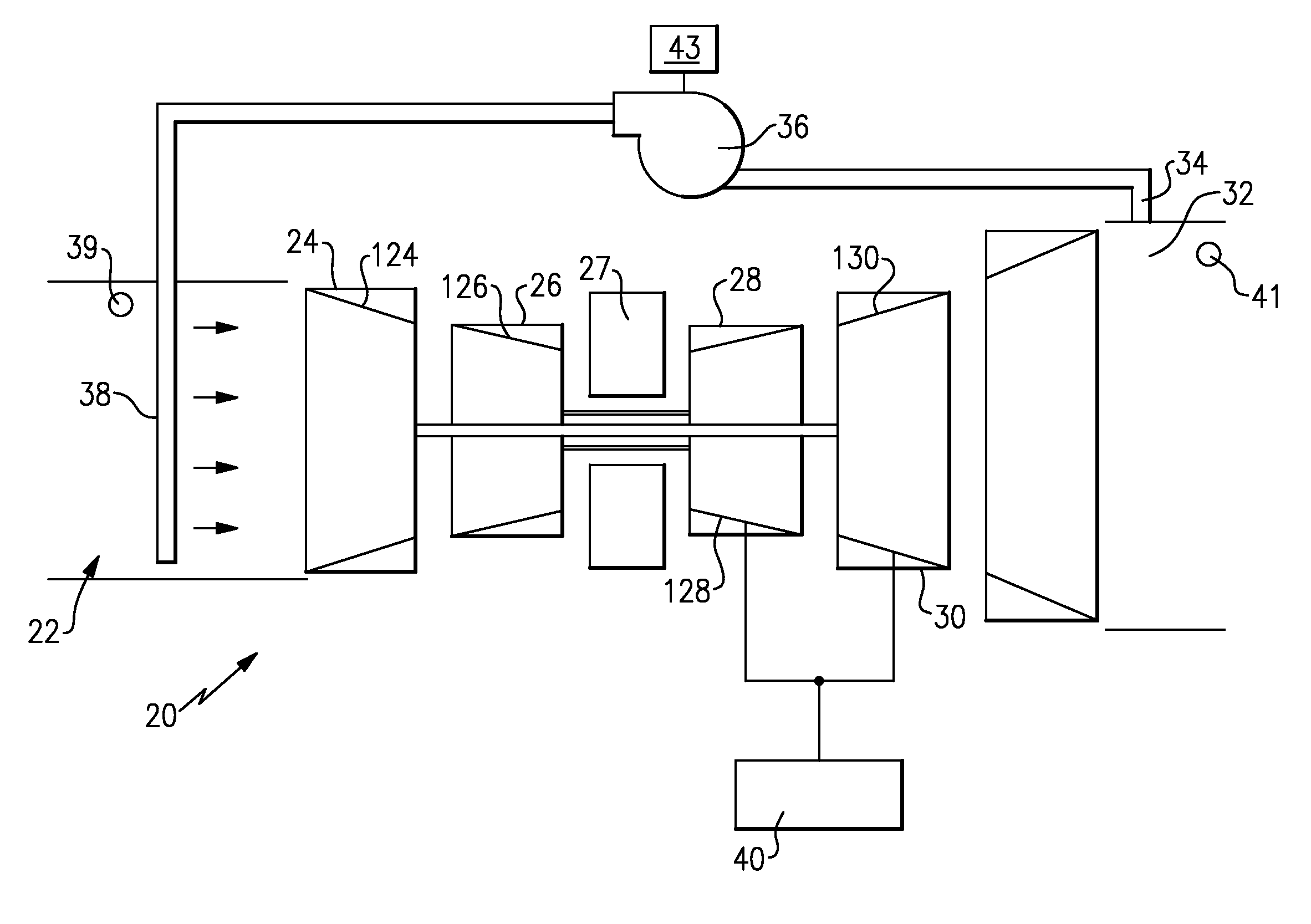
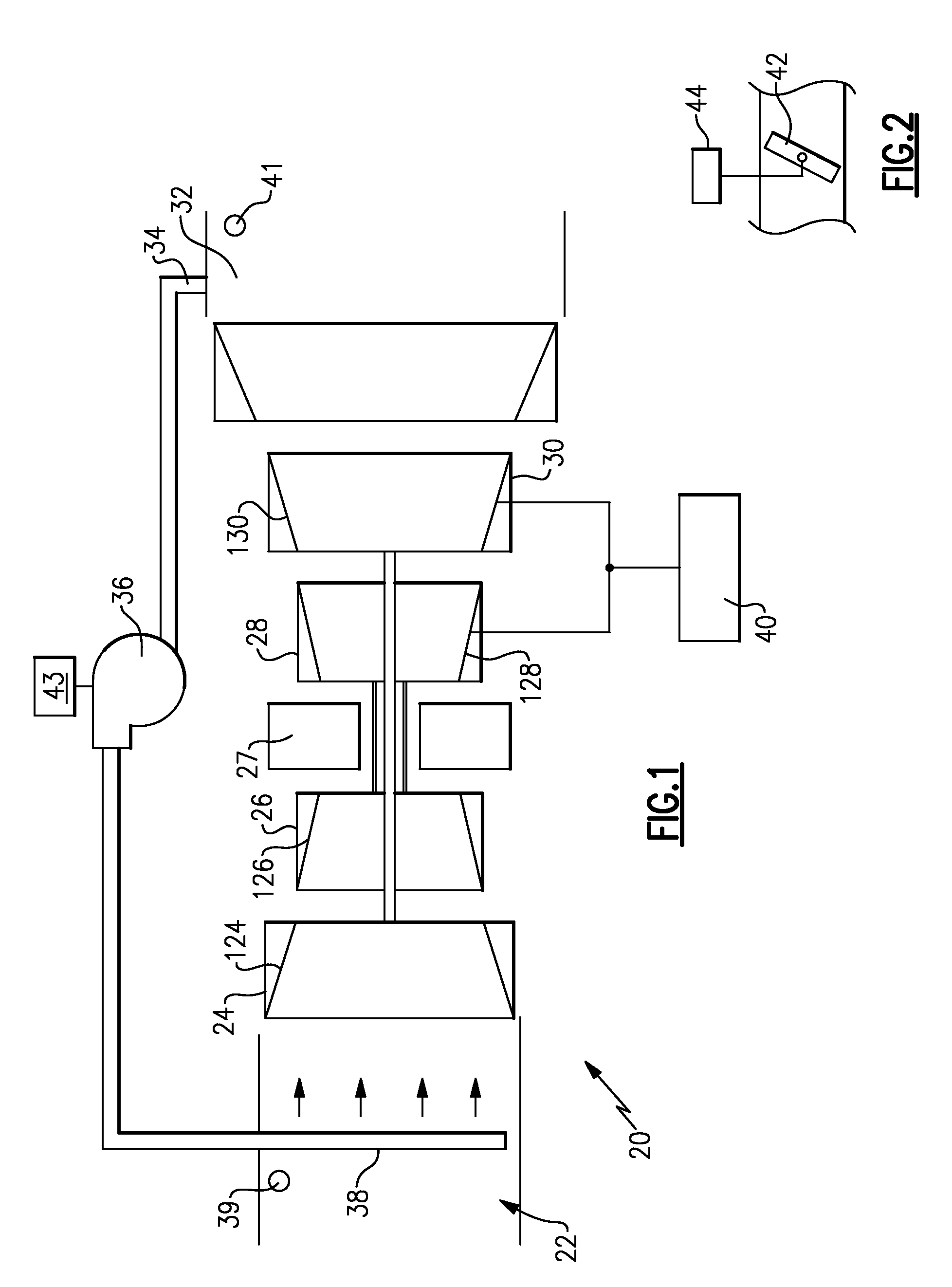
[0009]A gas turbine engine 20 is illustrated in FIG. 1. An inlet 22 delivers air to a low pressure compressor section 24, and downstream to a high pressure compressor section 26. Air from the compressor section 26 passes into a combustion section 27, and is mixed with fuel and burned. Preferably, the combustion section 27 is of a dry low NOx premix (DLN) type wherein fuel and air are premixed prior to combustion to assure flame temperatures are kept uniformly low to prevent formation of NOx. Products of this combustion pass over a high pressure turbine 28, and a low pressure turbine 30, driving the turbine rotors 128 and 130. The turbine rotors in turn drive compressor rotor 126 and compressor rotor 124, respectively. Downstream of the turbine sections the products of combustion pass into an exhaust 32. As shown, a tap line 34 taps a portion of the exhaust gas through a blower 36, and into a tap line 38. The tap line 38 bleeds gas into inlet 22 in controlled amounts. Although no fan...


PUM


Abstract

A gas turbine engine has an inlet for delivering air into a compressor section. The compressor section is connected to feed air into a combustion section, wherein the air mixes with fuel and combusts. The combustion section is connected to turbine rotors such that products of combustion can pass over the turbine rotors to drive the turbine rotors. An exhaust communicates with the turbine sections to receive the products of combustion. A bleed tap communicates the exhaust to the inlet. A control controls the amount of exhaust gasses tapped into the inlet to achieve desired operating conditions.

Description

BACKGROUND OF THE INVENTION[0001]The present invention relates generally to gas turbine engines and more particularly to an inlet air heating system of the engine and method of operating the same.[0002]Gas turbine engines are known, and typically include an inlet through which air passes to a compressor section. The air is compressed in the compressor section and passed downstream into a combustion section. In the combustion section, air is mixed with fuel and burned. Products of this combustion pass downstream across turbine rotors, to drive the rotors. A good deal of control is included in modern gas turbine engines.[0003]One recent advancement in gas turbine engines is the so-called dry low NOx or “DLN” combustion systems. These are often utilized in industrial gas turbine engines to achieve very low levels of NOx emissions, without any need for water injection. These engines typically have a very narrow operating range over which emissions are kept low.[0004]One way to increase ...

Claims


Application Information

Patent Timeline
Patent Type & Authority Applications(United States)
IPC IPC(8): F04D31/00
CPCF02C3/34F02C1/08F05D2270/082
Inventor SMITH, CRAIG F.
Owner PW POWER SYST LLC
Why Eureka
Try Eureka