[0013]The present invention presents a cheap and
effective solution for protecting RFIDs, which is perhaps the most compatible with current RF front ends found on tags. According to the inventive concept, a separation is created of the power supply from the power consumption by use of a double-buffering power supply mechanism consisting of a pair of capacitors switched by power transistors. At any stage in time, one
capacitor is charged by the reader's field while the other is being discharged by the circuit. With appropriate design, the present invention can almost eliminate the power consumption information. Moreover, this design involves changes only to the RF front-end of the tag, making it the quickest to roll out. To make this
countermeasure more cost effective, large flat capacitors can be attached to the plastic carrier next to the printed antenna. Note that unlike the case of smart cards, power analysis of RFID tags is likely to be carried out remotely (e.g., without opening in the store the product
enclosure in which the RFID tag is placed) and thus, one is less concerned about an attacker
cutting off the capacitors to get around the
countermeasure. Tags using this protective mechanism still have to take care that power consumption does not leak out through the intentional
backscatter modulation mechanism, which has to come out of the circuit proper and connect to the antenna.
[0014]Another major difference is that smart cards do not try to economize their power consumption, and with newer more powerful chips with security coprocessors, the power consumption gets even higher. It is thus difficult to run them from the tiny amount of power stored in a small
capacitor. In contradistinction, RFID's get their power from the
electromagnetic field around them, so they use very little power in order to be operable from a reader which is several meters away. This makes the protection technique more suitable for RFID tags than for smart cards.
[0015]Accordingly the present invention concerns a novel apparatus and method employed for protecting an RFID tag from
attack. The method and apparatus of the invention protects RFID tags against simple and differential power attacks. The invention is particularly useful regarding
inventory control systems and secure documents, such as e-passports.
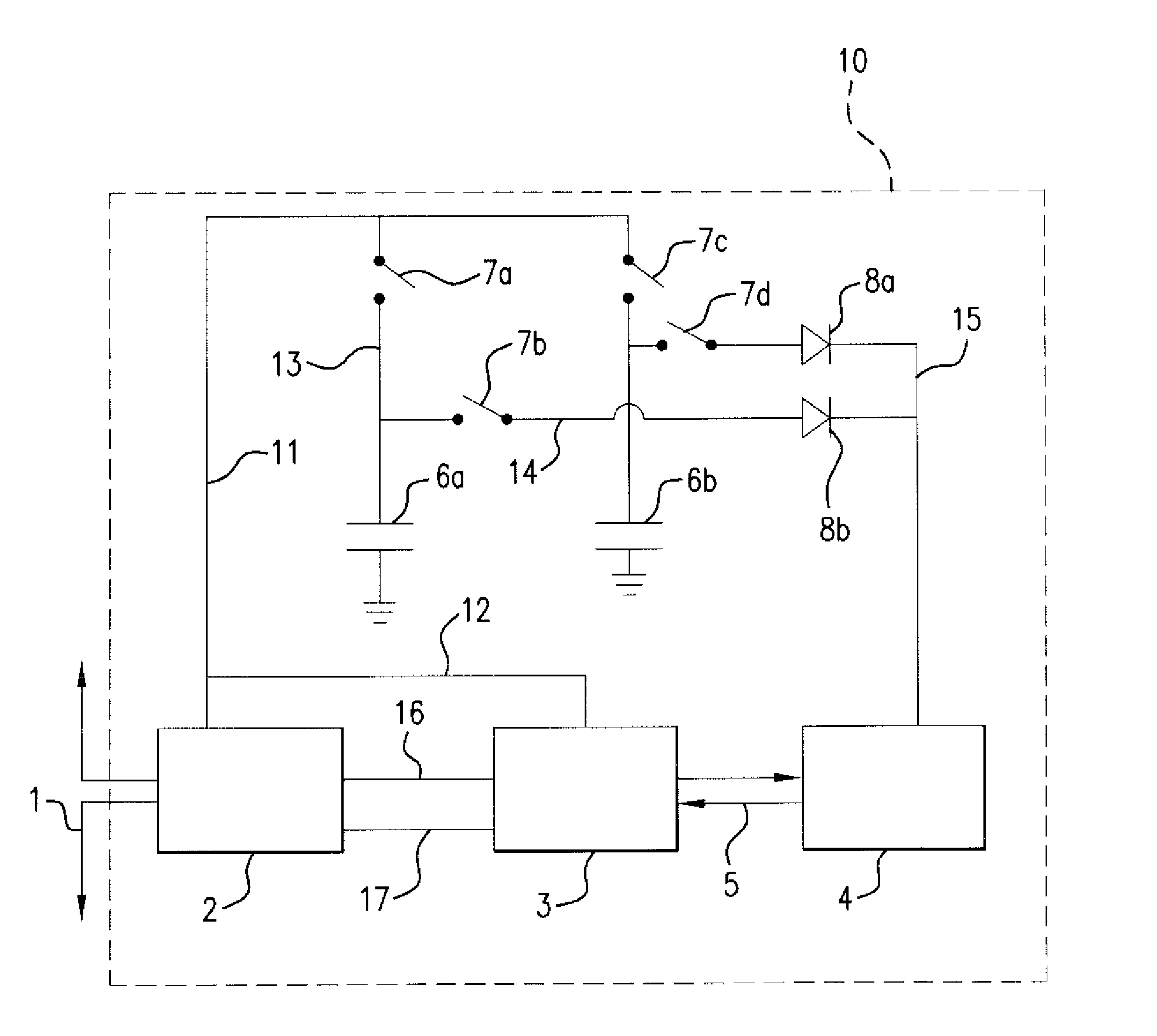
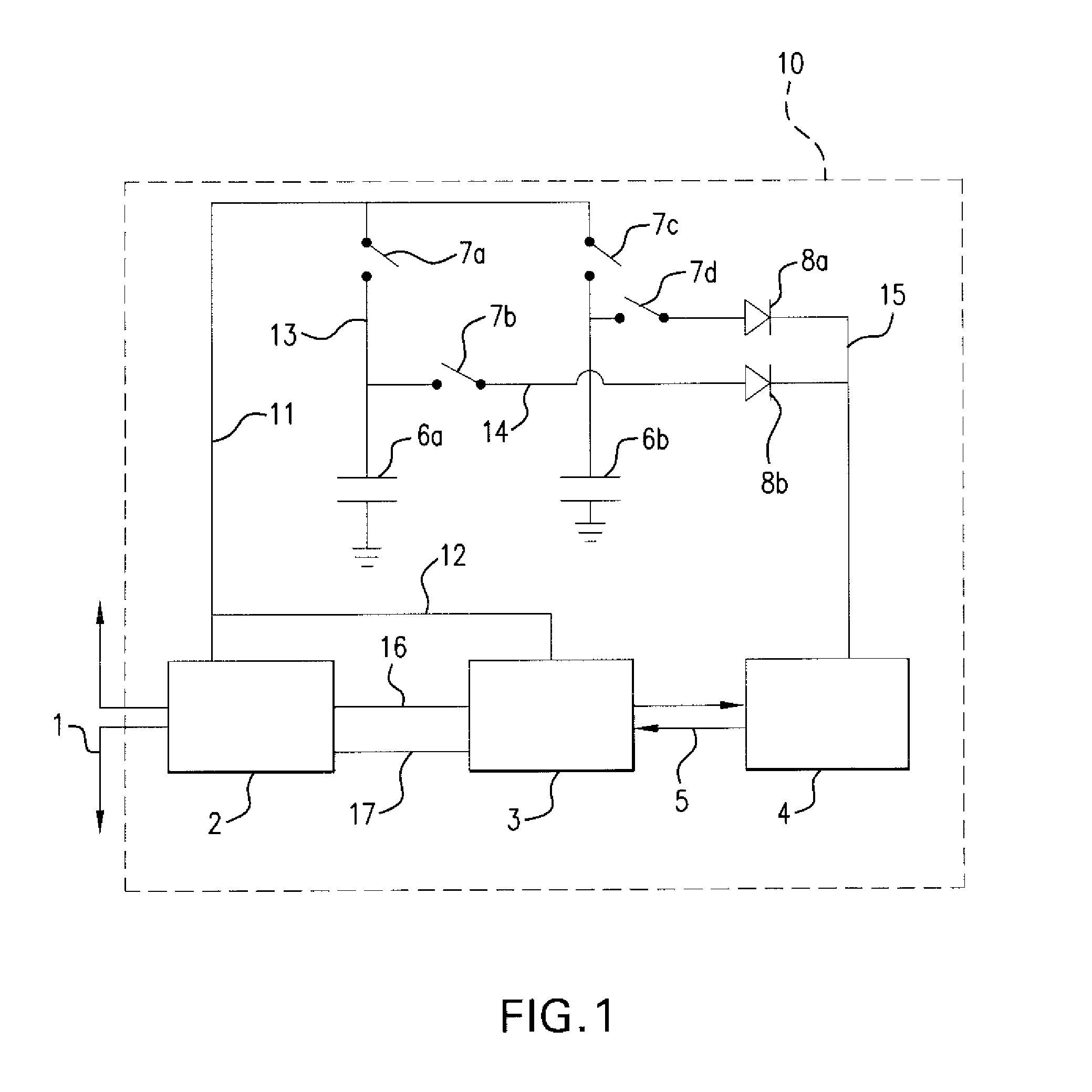
[0022]Yet, it is still a further object of the invention to provide apparatus comprising: a) an RFID tag including an antenna, a
power extraction circuit for generating power from an electromagnetic or
magnetic field of a reader with which it is associated, and a computational circuit, b) at least two capacitors, each coupled between the
power extraction circuit and the computational circuit, and c) switchover logic for alternately connecting the capacitors for at least one to
discharge to power the computational circuit while at least one other is being charged by the
power extraction circuit. The switchover logic can be such that the functions of the at least two capacitors are repeatedly reversed, and the RFID tag operates continuously. Also, the switchover logic can be such that the change of connection (switching of the capacitors) is triggered by the
voltage across one of the capacitors exceeding or dropping below a certain threshold. Still further, the switchover logic can be such that the change of connection is triggered by a preselected event. Also, the switchover logic can be such that the change of connection is triggered by the
voltage across at least one of the capacitors exceeding or dropping below a certain threshold at the beginning of a preselected event. In a preferred form of the invention, the switchover logic includes power transistors. A simple generalization of the present invention is to use three or more capacitors in such a way that at any time at least one of them is charging and at least one of the others is powering the computational element.

