Plant support pole and method of use

a technology for supporting poles and plants, applied in the field of plant support poles, can solve the problems of prone to rusting, prone to bending and rusting, and generally too short cages, and achieve the effect of convenient removal and storag

Inactive Publication Date: 2010-01-14
AIKEN JOHN E
View PDF25 Cites 11 Cited by
  • Summary
  • Abstract
  • Description
  • Claims
  • Application Information

AI Technical Summary

Benefits of technology

[0014]It is, therefore, one of the primary objects of the present invention to provide a durable, reusable, yet inexpensive and effective plant support pole or stake.
[0016]Still another object of the present invention is to provide a ready-to-use tomato stake with multiple plant support means over a long length allowing adjustable support of plant stems and branches at varying heights and horizontal distances from the stake.
[0017]Yet another object of the present invention is to provide an inexpensive, effective plant support system that can support to heights above 7 feet without the need of a ladder to install and use.
[0018]An additional object of the present invention is to provide a lightweight inexpensive tomato stake resistant to all kinds of decay and corrosion and hence reusable for many years.
[0020]Yet still another object of the present invention is to provide a plant support pole which is easy to remove and store for the next the season.

Problems solved by technology

The ties tend to slide down the stakes and the stakes and ties are prone to rotting.
The cages are generally too short, prone to bending and rusting, and also tend to tip over.
A vinyl coated triangular shaped cage has come on the market, but the legs still are susceptible to rust and bending.
All of the cage types suffer from the problem of some plant branches draping over the first rung and then hanging back down to the ground.
Also, the cages are difficult to install without breaking branches once the plant has grown considerably.
Besides being subject to getting rusted and bent at or below grade, this design would be susceptible to bending over or coming out of the ground the taller it gets.
For a tall stake or pole, this design would not be practical.
The hoops are of a fixed size, thus they may not extend out far enough in some cases, but if too large branches laden with tomatoes may drop down through.
There can be only one strap per section, thus support is limited and side branches would likely go unsupported.
Gardeners wanting a dozen of these support poles are likely to find the cost to be considerable due to the complexity of construction.
There are numerous other such prior art devices with the disadvantage of having to pull plant stems and branches up very close to the stake, which risks breakage and may bunch plant stems in an unnatural and crowded position.
Plant ties are located only at the joints between compartment, so the number and support locations are limited.
Fabrication of these appears to be involved and relatively expensive.
The support system of the '467 patent requires specially fabricated leg members which will add considerably to the cost.
Also, it would provide no aid in the watering or fertilizing of the plant.
This poses an inconvenience and a safety hazard, especially on sloped ground.
Also, the cost for some designs would make them impractical.
It can be extended to an installed height of 77 inches, but total cost is relatively high to get there.
Also, there is no way to deal with plant branches that grow through a window then droop toward the ground.
Preventing the plants from slumping or sliding down under the weight of the tomatoes is a common problem, and not adequately addressed by most of the prior art.

Method used


Image

  • Plant support pole and method of use
  • Plant support pole and method of use
  • Plant support pole and method of use

Examples


Embodiment Construction

, particularly, when such description is taken in conjunction with the attached drawing figures and with the appended claims.

BRIEF DESCRIPTION OF THE DRAWINGS

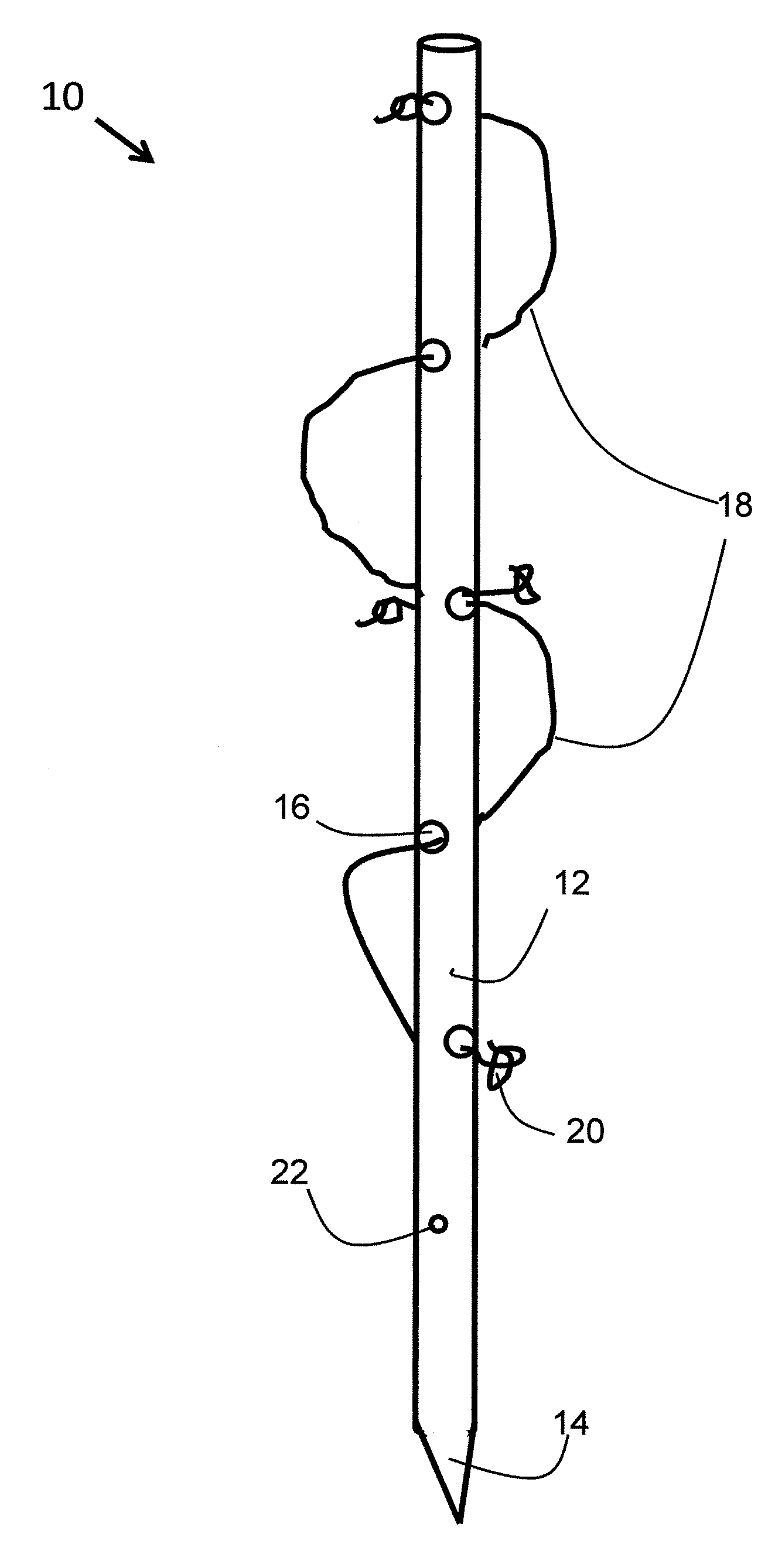
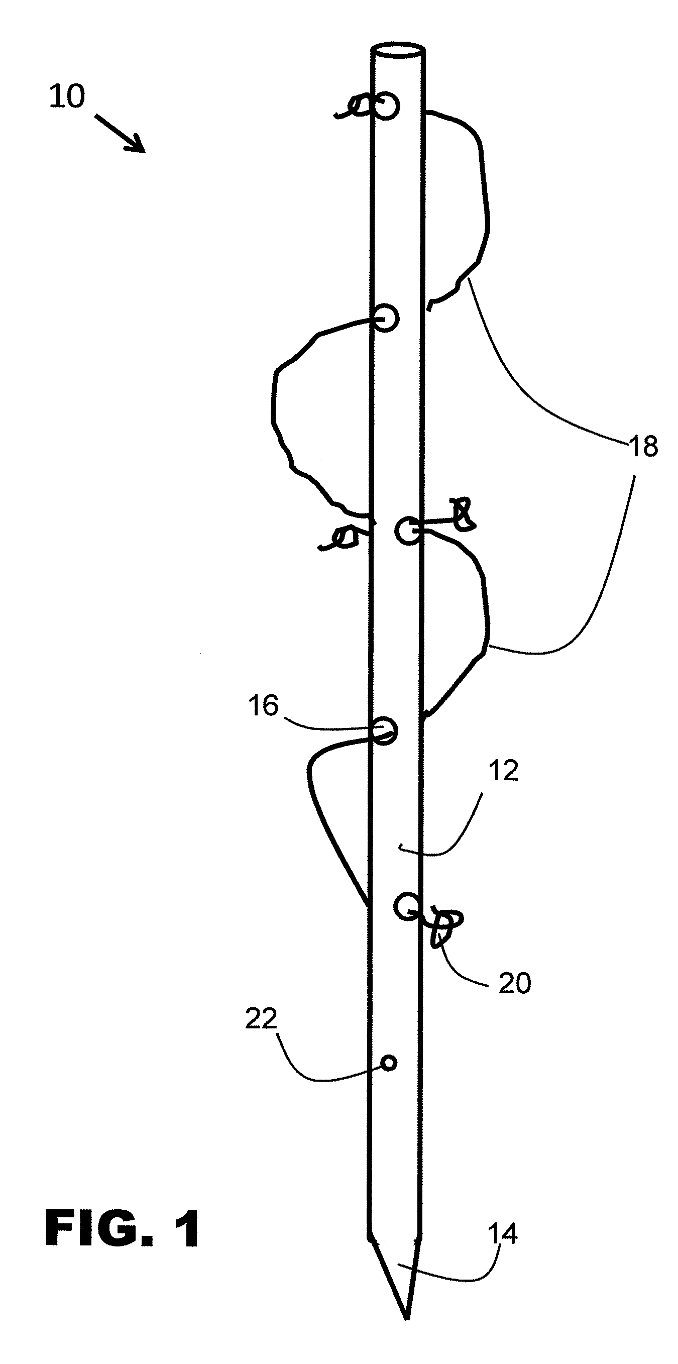
[0022]FIG. 1 is an elevation perspective view of the present invention.

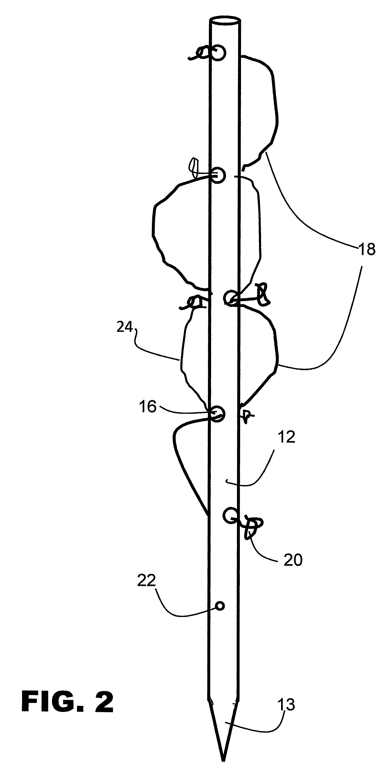
[0023]FIG. 2 presents an elevation perspective view of an alternative embodiment of the present invention.

[0024]FIG. 3 is an elevation view of a preferred extended embodiment of the present invention.

[0025]FIG. 4 provides perspective views of various means for securing the ends of the cord ties.

[0026]FIG. 5 provides an elevation view of the present invention with a plant illustrating support ways achievable with the present invention.

[0027]FIG. 6 presents an elevation perspective view of an alternative embodiment of the present invention.

[0028]FIG. 7 provides a detail elevation perspective view of an alternative embodiment of the present invention.

[0029]FIG. 8 provides a partial elevation perspective view of an alternative coupling means for the extension me...


PUM


Abstract

An apparatus for supporting plants growing from the ground includes an elongated rigid pole with a plurality of axially-spaced apertures along much of the pole. Flexible cord ties are threaded in a spiral fashion through at least three apertures in the long wall of the elongated pole, and knots at the ends are tied around plant stems or branches thereby preventing disengagement from the holes and simultaneously supporting the plant. One end of the elongated pole is cut at an angle to the axis to form a point.

Description

CROSS REFERENCE TO RELATED APPLICATION[0001]This patent application is related to and claims priority from U.S. Provisional Patent Application Ser. No. 61 / 134,482 filed Jul. 10, 2008.FIELD OF THE INVENTION[0002]The present invention relates, in general, to devices for supporting plants and, more particularly, this invention relates to inexpensive reusable poles for supporting tomato and other garden plants.BACKGROUND OF THE INVENTION[0003]Prior to the conception and development of the present invention, home gardeners have been using various means for keeping most of their tomato plants off the ground while growing and particularly when the tomatoes begin appearing on the plants. This helps the plants to grow, but mostly it guards against the vegetable resting on the ground and rotting or getting infested with insects. For many decades, wooden stakes have been driven in along side each plant, and then rope, twine, or cloth strips are used to try to hold the plant stems near the stak...

Claims


Application Information

Patent Timeline
Patent Type & Authority Applications(United States)
IPC IPC(8): A01G17/14A01G17/04
CPCA01G9/128A01G9/122
Inventor AIKEN, JOHN E.
Owner AIKEN JOHN E
Why Eureka
Try Eureka