
Torque sensor with reduced susceptibility to failure

a sensor and susceptibility technology, applied in the field of sensor arrangement, can solve the problems of high reliability and fail-safety achieve the effects of improving the intrinsic safety of the sensor arrangement, improving measurement precision, and more robustness

Inactive Publication Date: 2010-01-14
CONTINENTAL TEVES AG & CO OHG
View PDF12 Cites 29 Cited by
  • Summary
  • Abstract
  • Description
  • Claims
  • Application Information

AI Technical Summary

Benefits of technology

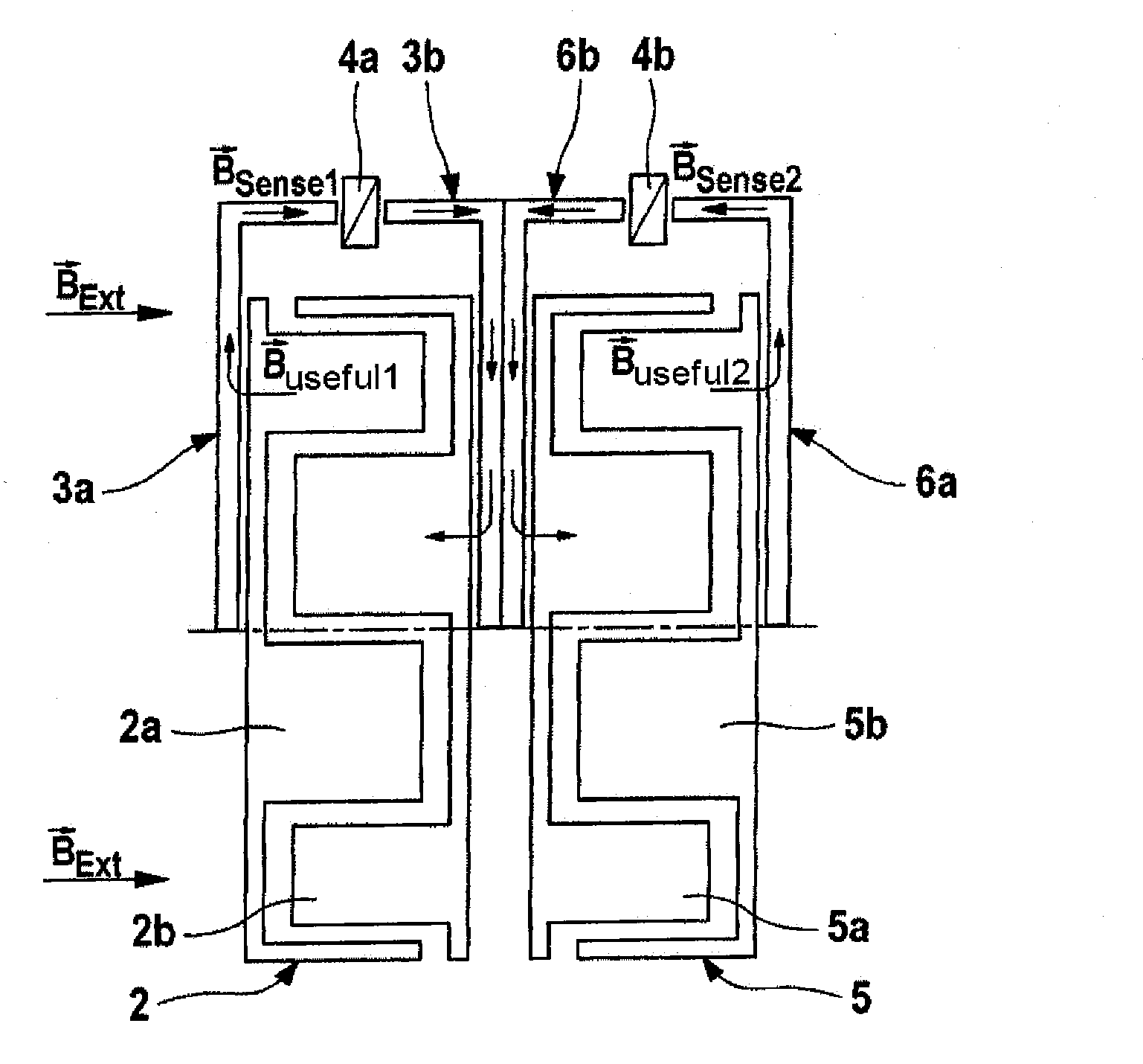
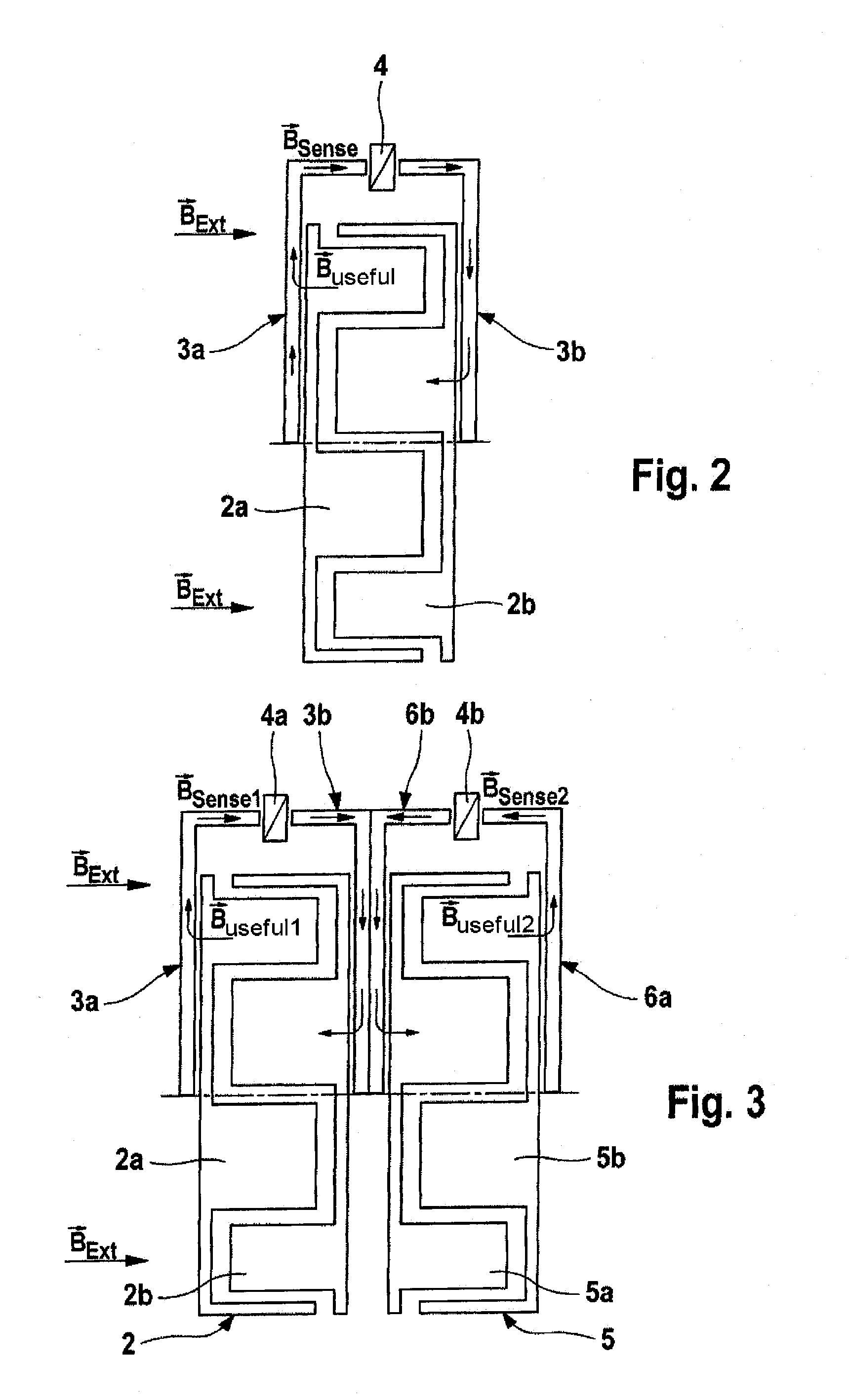
The invention provides a sensor arrangement for measuring torque on a shaft that is less susceptible to external magnetic fields. This is achieved by arranging two stators on the shaft section, with one stator element on each shaft section. The stator elements have magnetic circuits that detect the magnetic field caused by the magnetic encoder. The arrangement has redundant detection of the torque to ensure high reliability and fail-safe operation. The magnetic encoder has two or more magnetic encoders or encoder rings that are arranged alongside one another on the shaft section. The stator elements are associated with flux concentrators that supply the magnetic field to the stator elements. The sensor arrangement has at least one common magnetic field sensor element that is positioned close to the stator elements to detect any external magnetic field that may affect the sensor arrangement.

Problems solved by technology

This redundancy of the two magnetic circuits results in relatively high reliability and fail-safety of the sensor arrangement.

Method used


Image

  • Torque sensor with reduced susceptibility to failure
  • Torque sensor with reduced susceptibility to failure
  • Torque sensor with reduced susceptibility to failure

Examples


Embodiment Construction

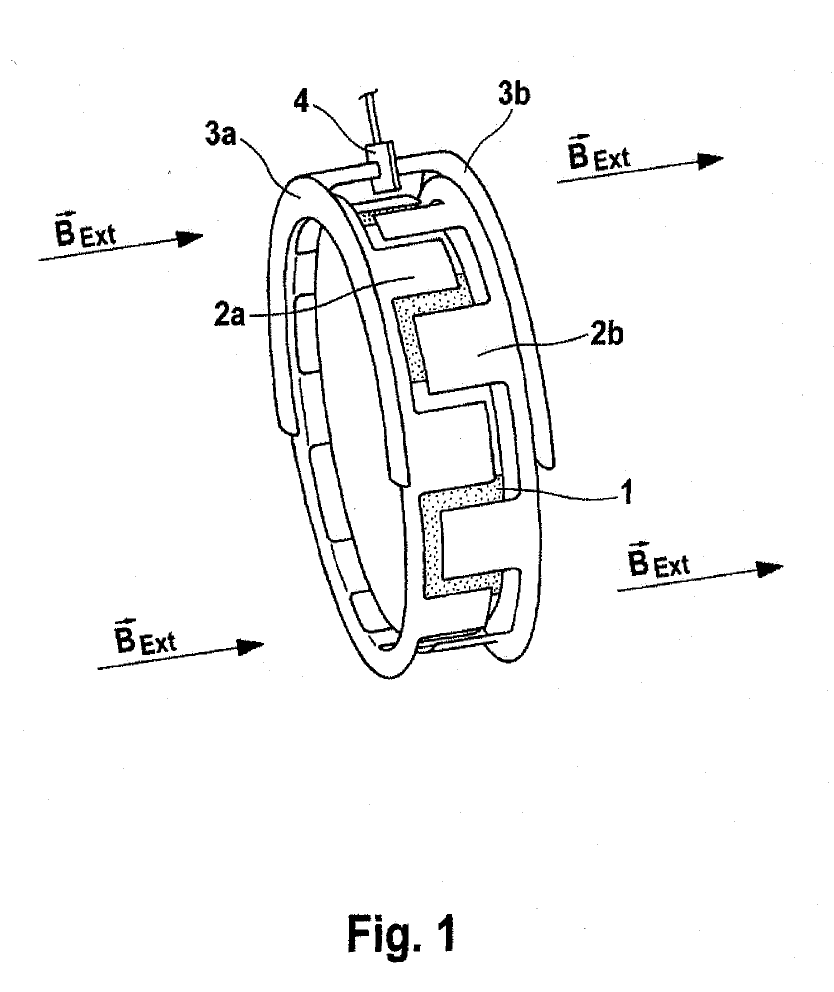
[0038]FIG. 1 illustrates a sensor according to the prior art. A magnetic multipole encoder ring 1 produces a magnetic field. A magnetic flux is produced through the stator by relative rotation of the stator elements 2a and 2b relative to an encoder ring 1, as a consequence of twisting of a torsion rod, which is not illustrated, by a torque acting on a shaft. In this case, the encoder or multipole encoder ring 1 as well as stator elements 2a, 2b are each arranged on a different shaft section of a shaft, with these two shaft sections being connected to one another by means of the torsion rod. The lines of force of the magnetic flux run from the multipole encoder ring 1 through the stator element 2a. The stator elements 2a, 2b have a respectively associated concentrator element 3a, 3b of a flux concentrator. The concentrator element 3a concentrates the flux and passes it in a concentrated form through a Hall element 4 in the concentrator element 3b. From there, the magnetic flux is pas...


PUM

PropertyMeasurementUnit
magnetic flux densityaaaaaaaaaa
magnetic fieldaaaaaaaaaa
torqueaaaaaaaaaa

Abstract

A sensor arrangement with relatively low disturbance susceptibility for measurement of a torque acting on a shaft, wherein the shaft has a first shaft section and a second shaft section and these two shaft sections can rotate with respect to one another, having at least one magnetic encoder which is arranged on the first shaft section, and having a stator which is arranged on the second shaft section, wherein the stator has two stator elements which each have projecting fingers, wherein at least one additional, second stator, likewise having two stator elements which each have projecting fingers, is arranged on the second shaft section, and these stators are associated with the magnetic encoder.

Description

CROSS REFERENCE TO RELATED APPLICATIONS[0001]This application is the U.S. national phase application of PCT International Application No. PCT / EP2008 / 050920, filed Jan. 28, 2008, which claims priority to German Patent Application No. DE102007005220.2, filed Jan. 29, 2007 and German Patent Application No. DE102007057050.5, filed Nov. 27, 2007, the contents of such applications being incorporated by reference herein.BACKGROUND OF THE INVENTION[0002]1. Field of the Invention[0003]The invention relates to a sensor arrangement for measurement of a torque acting on a shaft and to the use of the sensor arrangement in motor vehicles.[0004]2. Description of the Related Art[0005]In motor vehicles, it is frequently necessary to measure the torque acting on a shaft. This relates in particular to the steering shaft in the steering system of a motor vehicle, with the steering torque being provided as a measurement variable for a number of motor vehicle control systems. The steering torque is in th...

Claims


Application Information

Patent Timeline
Patent Type & Authority Applications(United States)
IPC IPC(8): G01L3/10
CPCG01L3/104G01L5/221
Inventor ANTONI, HENRIKRINK, KLAUS
Owner CONTINENTAL TEVES AG & CO OHG
Learn More