Device for displacing and positioning an object in space

a technology for positioning objects and objects, applied in mechanical control devices, process and machine control, instruments, etc., can solve the problems of limited service life prediction, limited dimensional accuracy of prestressing, and inability to ensure the detectability of falling components, etc., to facilitate decoupling, facilitate disassembly, and improve the degree of reliability

Inactive Publication Date: 2010-01-14
ROBERT BOSCH GMBH
View PDF20 Cites 38 Cited by
  • Summary
  • Abstract
  • Description
  • Claims
  • Application Information

AI Technical Summary

Benefits of technology

[0032]Another advantage of the invention is that if an overload occurs in the joints on one side of the parallelogram, then the joints on the other side also open slightly so that here, too, a facilitated decoupling occurs. As a result, with the desired load, the decoupling occurs with a greater degree of reliability.
[0033]The prestressing elements can be manufactured out of suitable friction-modified plastics; it is possible to use two different suitable plastics so that no bearing shell or lubrication is required for the joints thanks to the material pairing selected for the prestressing elements.
[0034]In the simplest case, it is also possible for one clamping element to be provided in the middle of the rods, but this eliminates the advantages of the easy disassembly. The rods must be more powerfully “deflected,” which negatively affects the precision of the robot, and the connecting element must be able to absorb a torsion moment transverse to the rod axes in order to prevent a twisting of the connecting rods in this direction.

Problems solved by technology

Limited dimensional accuracy of the prestressing due to material tolerances.
With gradual destruction of the prestressing element, it is not possible to assure detectability of falling components in products to be processed.
Limited possibility of predicting the service life due to the above-mentioned conditions.
Hygiene requirements make it impossible to use conventional spring elements such as steel springs.

Method used


Image

  • Device for displacing and positioning an object in space
  • Device for displacing and positioning an object in space
  • Device for displacing and positioning an object in space

Examples


Embodiment Construction

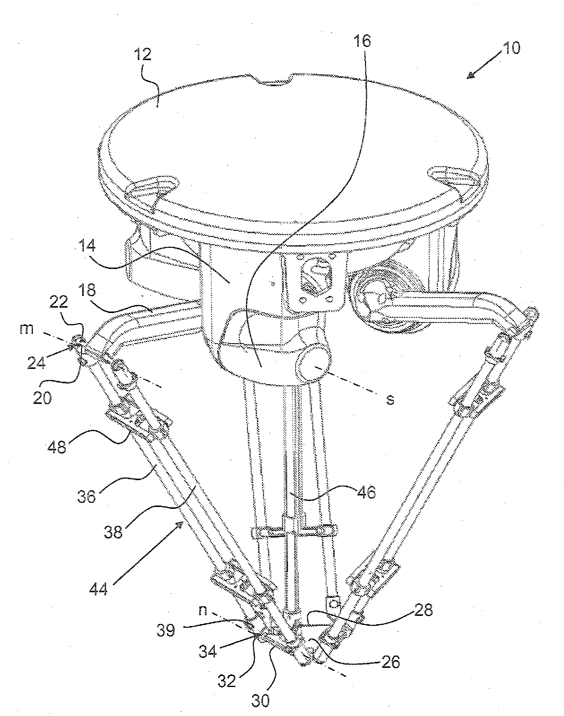
[0039]A delta robot 10 shown in FIG. 1 has a base element 12 with a horizontal mounting plane and three mounts 14 protruding from the base element 12. each for accommodating a respective motor / transmission unit 16. Each motor / transmission unit 16 has a transmission shaft that defines a transmission axis s and supports an actuating arm 18 that is able to pivot around the transmission axis s. The three transmission axes s lie in a plane parallel to the mounting plane of the base element 12 and their intersection points constitute the vertices of an equilateral triangle. At the free end of each actuating arm 18, there is a first joint rod 20 that defines a first articulation axis m oriented parallel to the transmission axis s. Each first joint rod 20 has a first joint part 22 at each of its two ends, each belonging to a first ball joint 24. The first joint parts 22 arranged in pairs are situated mirror symmetrically to each other in relation to a vertical plane; the three vertical plan...


PUM


Abstract

The invention relates to a device for displacing and positioning an object in a space, having at least three actuating arms that can pivot about a transmission axis. Each arm is connected to a motor unit/transmission unit. A carrier element is provided in order to arrange at least one gripping element for gripping the object. Each actuating arm, on the free ends thereof, has a first articulated axis that is parallel to the transmission axis with first articulated parts arranged at a distance from each other, of a first ball joint. The carrier element has a second articulated axis associated with each actuating arm with first articulated parts that are arranged at a distance in relation to each other, of a second ball joint. The first articulated axis is connected to the second articulated axis by a pair of connecting bars which include terminal second articulated parts. The terminal second articulated parts of the connecting bars form the first and second ball joints with the first articulated parts on the first articulated axis and the first articulated parts on the second articulated axis. The connecting bars for stabilizing the ball joints are connected together. According to the invention, the connecting bars are made of an essentially elastic material and are connected together by at least one prestressing element made of an essentially stiff material.

Description

TECHNICAL FIELD[0001]The invention relates to a device for moving and positioning an object in space, having at least three actuating arms that are each connected to a motor / transmission unit and are pivotable around a transmission axis, a support element provided for arranging at least one gripping mechanism for gripping the object; at its free end, each actuating arm has a first articulation axis extending parallel to the transmission axis, with first joint parts spaced apart from each other, each belonging to a respective first ball joint; the support element has a second articulation axis associated with each actuating arm, with first joint parts spaced apart from each other, each belonging to a respective second ball joint; the first articulation axis is connected to the second articulation axis by means of a pair of connecting rods that have second joint parts at the ends and, together with the first joint parts on the first articulation axis and the first joint parts on the s...

Claims


Application Information

Patent Timeline
Patent Type & Authority Applications(United States)
IPC IPC(8): B25J17/00B25J18/00
CPCB25J17/0266B25J9/0051Y10T74/20317Y10T74/20329Y10T74/20305
Inventor BREU, MICHAEL
Owner ROBERT BOSCH GMBH
Why Eureka
Try Eureka