Positioning system for use in wind turbines and methods of positioning a drive train component

a technology of positioning system and drive train, which is applied in the field of wind turbines, can solve the problems of large components being subjected to increased loads, drive train components may become worn and/or damaged, and significant fatigue cycles on the drive train components, etc., and achieve the effect of convenient removal and installation of the componen

Inactive Publication Date: 2012-05-31
GENERAL ELECTRIC CO
View PDF2 Cites 26 Cited by
  • Summary
  • Abstract
  • Description
  • Claims
  • Application Information

AI Technical Summary

Benefits of technology

[0005]In another aspect, a positioning system for use in a wind turbine is provided. The wind turbine includes a rotor, a drive train assembly supported from a support frame, and a drive shaft rotatably coupled between the rotor and the drive train assembly. The positioning system includes a positioning assembly coupled to a component of the drive train assembly and the support frame for supporting the component from the support frame. An alignment assembly is coupled between the positioning assembly and the component. The alignment assembly is configured to adjust an orientation of the component within multiple planes to facilitate removing and installing the component without removing the rotor from the wind turbine.

Problems solved by technology

However, the larger components are often subjected to increased loads (e.g., asymmetric loads) that result from wind shears, yaw misalignment, and / or turbulence, and the increased loads have been known to contribute to significant fatigue cycles on the drive train components, i.e., the gearbox and / or the generator.
Over time, the drive train components may become worn and / or damaged.
In some wind turbines, the blades are between 60 and 100 meters in length, and as such, repairing worn or damaged drive train components can be costly and time-consuming.

Method used


Image

  • Positioning system for use in wind turbines and methods of positioning a drive train component
  • Positioning system for use in wind turbines and methods of positioning a drive train component
  • Positioning system for use in wind turbines and methods of positioning a drive train component

Examples


Embodiment Construction

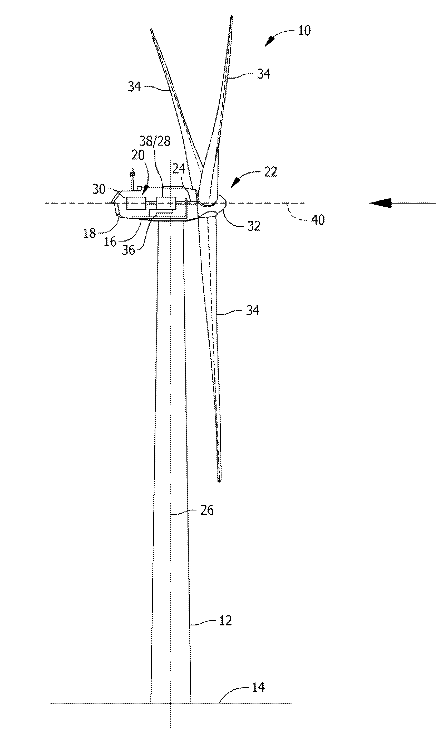
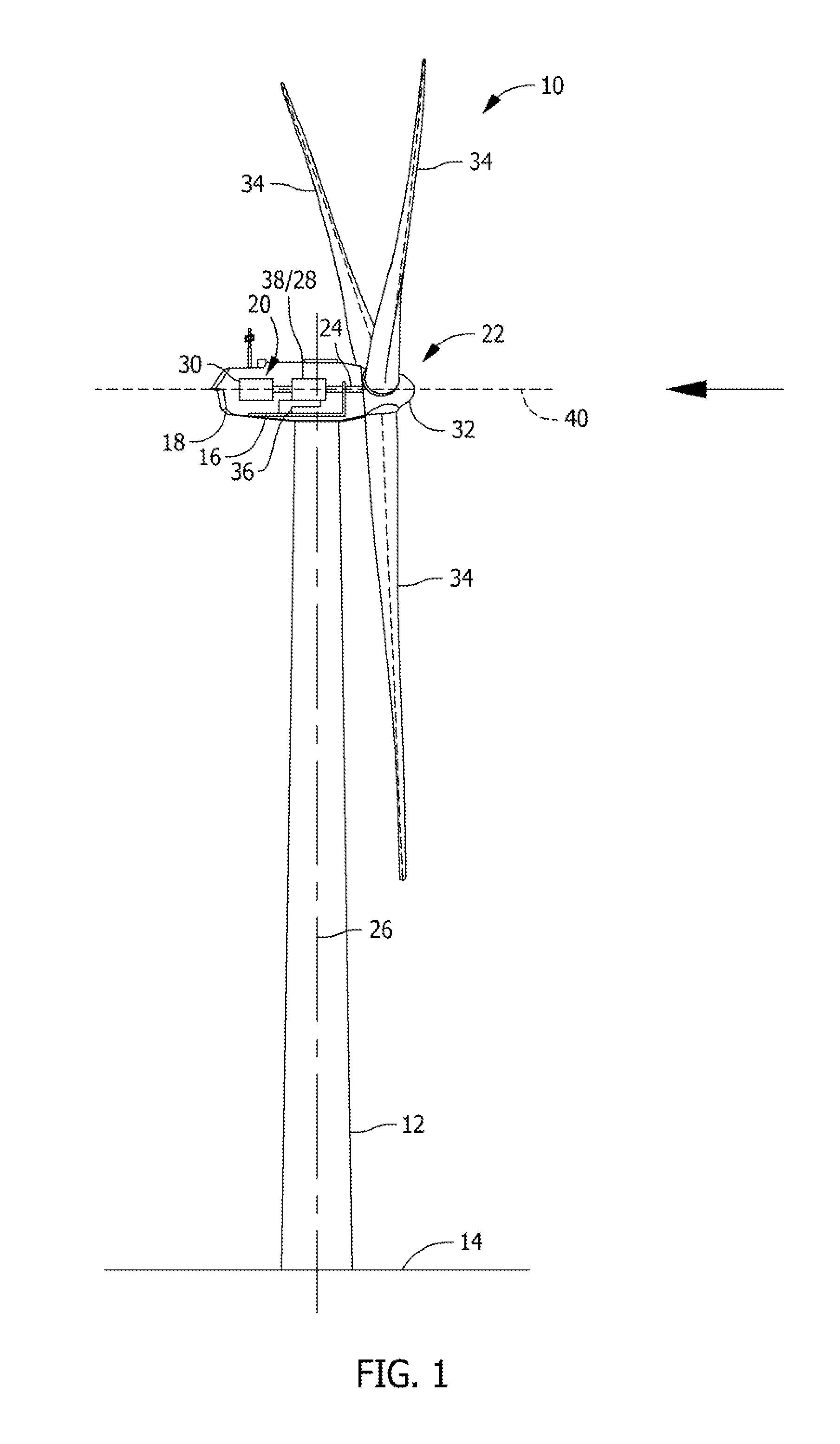
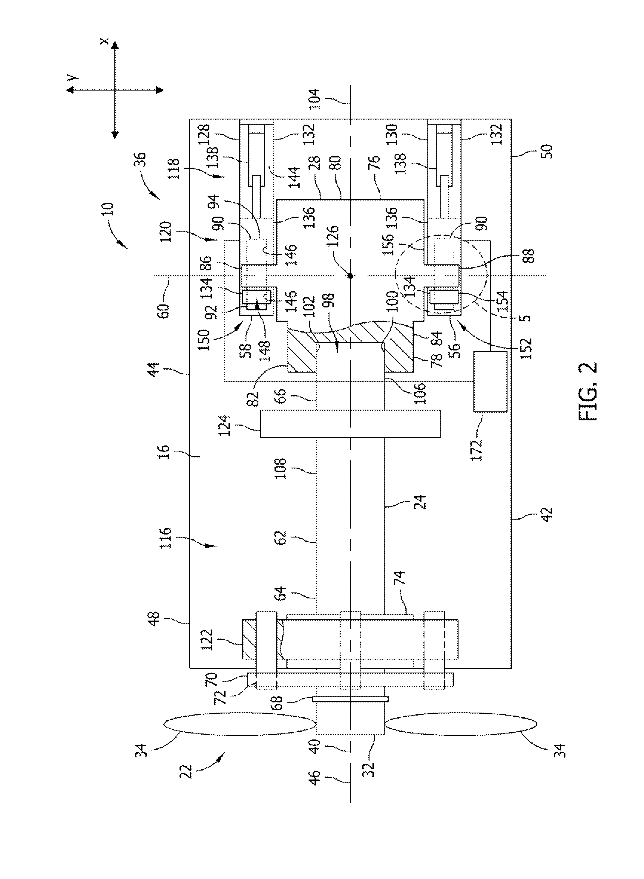
[0014]The exemplary methods and systems described herein overcome at least some disadvantages of known wind turbines by providing a positioning system that is configured to remove and / or replace a drive train component uptower of a wind turbine. Moreover, the positioning system described herein includes an alignment assembly that is adapted to be coupled to a drive train component, and is configured to adjust an orientation of the component within multiple planes to facilitate coupling and / or decoupling the component from the drive shaft without removing the rotor from the drive shaft. By providing a positioning system that enables a drive train component to be coupled and / or decoupled from the drive shaft uptower of the wind turbine, the need for large lifting cranes is reduced. As such, the cost and manpower required to remove and / or replace the drive train component is significantly reduced.

[0015]As used herein, the term “uptower” is intended to be representative of any location ...


PUM

PropertyMeasurementUnit
lengthaaaaaaaaaa
lengthaaaaaaaaaa
lengthaaaaaaaaaa

Abstract

A positioning system for use in a wind turbine is described herein. The wind turbine includes a rotor, a drive train assembly that is supported from a support frame, and a drive shaft rotatably coupled between the rotor and the drive train assembly. The positioning system includes an alignment assembly that is coupled to a component of the drive train assembly. The alignment assembly is configured to adjust an orientation of the component with respect to the drive shaft with the drive shaft at least partially inserted within the component.

Description

BACKGROUND OF THE INVENTION[0001]The subject matter described herein relates generally to wind turbines, and more specifically, to a positioning system for use in removing a component of a drive train assembly from the wind turbine.[0002]At least some known wind turbines include a nacelle fixed atop a tower, a drive train assembly positioned within the nacelle, and a rotor assembly coupled to the drive train assembly with a rotor shaft. At least some known drive train assemblies include a gearbox that is coupled to the drive shaft, and a generator coupled to the gearbox. In known rotor assemblies, a plurality of blades extend from a rotor, and each are oriented such that wind passing over the blades turns the rotor and rotates the shaft, thereby driving the generator to generate electricity.[0003]Because many known wind turbines provide electrical power to utility grids, at least some wind turbines have larger components (e.g., rotors in excess of thirty-meters in diameter) that fac...

Claims


Application Information

Patent Timeline
Patent Type & Authority Applications(United States)
IPC IPC(8): B23Q3/00
CPCF03D1/003F05B2260/30Y10T29/53978Y02E10/722Y10T29/49895F03D11/02F03D15/00F03D80/50F05B2260/31Y02E10/72F03D9/25F03D15/10F03D80/70
Inventor NEUMANN, ULRICH
Owner GENERAL ELECTRIC CO
Why Eureka
Try Eureka