Atmospheric heater

a heater and atmosphere technology, applied in the field of atmospheric heaters, can solve the problems that modern heaters cannot generate deep romantic lighting, deny modern lighting, and the atmosphere or romantic effect provided by a fireplace cannot be made by modern heaters, so as to not consume a great amount of energy, and enhance the atmospheric lighting effect.

Inactive Publication Date: 2010-01-14
GRAND HALL ENTERPRISE COMPANY
View PDF33 Cites 2 Cited by
  • Summary
  • Abstract
  • Description
  • Claims
  • Application Information

AI Technical Summary

Benefits of technology

[0007]The primary purpose of the present invention is to provide an atmospheric heater that gives off dim lighting of vertical bars from opposite sides thereof to enhance an atmospheric lighting effect. The heater has opposite side walls each forming therein a vertical groove for receiving a retention rail in such a way that the retention rail has an opening that is exposed outside the side wall of the heater for slidably receiving and retaining a fogged light-transmitting tube, which is spaced from a bottom wall of the retention rail to define a first channel. A circuit board that carries an array of light-emitting diodes is positioned and pinchingly fixed inside the fogged light-transmitting tube at one side that is opposite to the side where light is given off to thereby form a second channel between the circuit board and the wall of the fogged light-transmitting tube where the light is given off. The circuit board comprises a power cable extending through the fogged light-transmitting tube and the retention rail into a heater enclosure to connect to a power source. Thus, heat emitted from the heater travels through the first channel and the second channel for penetrating vertically in a down-to-up direction to generate a chimney effect for dissipation in order to prevent the light-emitting diodes from over-heating and burnout during the operation thereof and also enhancement of atmospheric lighting effect is realized. This is the primary objective of the present invention.
[0008]The atmospheric heater in accordance with the present invention employs light-emitting diodes as a light source for atmospheric lighting emitted from sides of the heater enclosure. Light-emitting diodes are considered the most power-saving illumination devices and do not consume a great amount of energy, whereby safety of lighting decoration and less consumption of power can both be realized. This is another objective of the present invention. Further, the atmospheric heater in accordance with the present invention may further form a third channel inside the fogged light-transmitting tube opposite to the space between the circuit board and the side wall of the fogged light-omitting tube where the light is emitted, whereby the heat that is emitted from the heater is guided to penetrate in a down-to-up direction through the first channel, the second channel, and the third channel to provide a chimney effect for heat dissipation. Since the number of partitioned channels is increased, the light-emitting diodes can be better protected from over-heating and burnout during the operation thereof. This is a further objective of the present invention.
[0009]Further, the atmospheric heater in accordance with the present invention may farther comprises at least one heat dissipation block that has a corrugated and thus increased surface area and is of excellent thermal conductivity received in the third channel to enhance heat dissipation performance, allowing for efficient heat conduction and temperature reduction through the third channel during operation of the light-emitting diodes and the heater. This is yet a further objective of the present invention.

Problems solved by technology

However, atmospheric or romantic effect that is provided by a fireplace cannot be made by the modern heaters.
Although lighting can be easily made with indoor lighting facility in the nighttime, yet people often deny such modern lighting, which is often of more than desired brightness, when they are sitting in front of a fireplace and surrounded by such a romantic atmosphere.
The modern heaters do not have means to generate deep and romantic lighting resembling the dim and jumping light from a fireplace.

Method used


Image

  • Atmospheric heater
  • Atmospheric heater
  • Atmospheric heater

Examples


Embodiment Construction

[0020]The following descriptions are of exemplary embodiments only, and are not intended to limit the scope, applicability or configuration of the invention in any way. Rather, the following description provides a convenient illustration for implementing exemplary embodiments of the invention. Various changes to the described embodiments may be made in the function and arrangement of the elements described without departing from the scope of the invention as set forth in the appended claims.

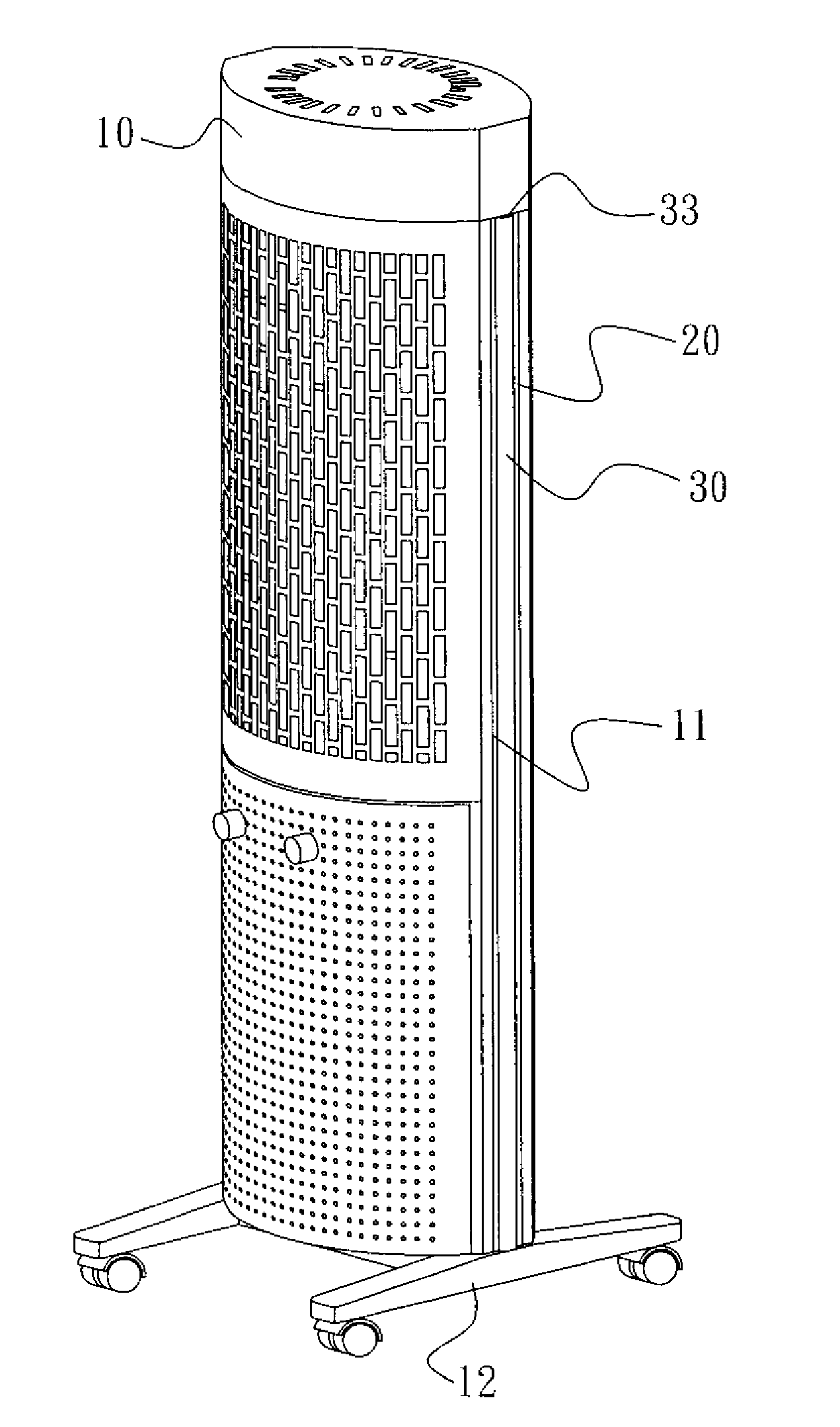
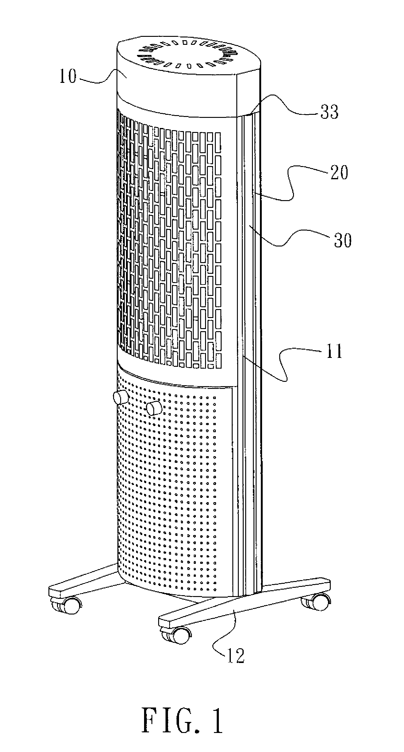
[0021]With reference to the drawings and in particular to FIGS. 1-5, of which FIG. 1 is a perspective view showing an atmospheric heater constructed in accordance with the present invention, FIG. 2 is a front view of the atmospheric heater of the present invention, FIG. 3 is an exploded view of the atmospheric heater with two side fogged light-transmitting tubes detached, FIG. 4 is a cross-sectional view showing the fogged light-transmitting tube of FIG. 3 fit in a retention rail, together with a...


PUM


Abstract

An atmospheric heater has opposite side walls each forming a groove for receiving a retention rail with an opening of the retention rail exposed to receive and retain a fogged light-transmitting tube, which is spaced from a bottom wall of the retention rail to define a first channel. A circuit board that carries light-emitting diodes is fixed inside the tube and opposite to the tube wall where light is given off to thereby form a second channel between the circuit board and the tube wall. Heat emitted from the heater travels through the first and second channels for penetrating vertically in a down-to-up direction to generate a chimney effect for heat dissipation in order to prevent the light-emitting diodes from over-heating and burnout during the operation thereof and also provide a dim lighting effect on opposite sides of the heater.

Description

BACKGROUND OF THE INVENTION[0001](a) Technical Field of the Invention[0002]The present invention relates to an atmospheric heater having an enclosure having opposite side walls from which vertical bar like dim lighting is given off to provide an atmospheric lighting effect and form atmospheric lighting decoration.[0003](b) Description of the Prior Art[0004]A heater is a commonly used warm keeping device. Besides the long known wall fireplace, various newly developed heaters are also available, such as gas heater, electrically-heated oil heater, and electrical heater. These modern heaters are advantageous in maneuverability in accordance with space arrangement and partition requirement. However, atmospheric or romantic effect that is provided by a fireplace cannot be made by the modern heaters.[0005]Although lighting can be easily made with indoor lighting facility in the nighttime, yet people often deny such modern lighting, which is often of more than desired brightness, when they ...

Claims


Application Information

Patent Timeline
Patent Type & Authority Applications(United States)
IPC IPC(8): H05B1/00
CPCF24H3/002
Inventor HOME, WILLIAM
Owner GRAND HALL ENTERPRISE COMPANY
Why Eureka
Try Eureka