
Piezoelectric Motor and Method of Manufacturing the Same

Inactive Publication Date: 2010-01-14
MURATA MFG CO LTD
View PDF5 Cites 16 Cited by
  • Summary
  • Abstract
  • Description
  • Claims
  • Application Information

AI Technical Summary

Benefits of technology

[0015]The present invention provides a piezoelectric motor with which troublesome wiring operations for manufacturing the stator can be omitted and the number of components can be reduced, thereby resolving the above-described problems of the related art. The piezoelectric motor can be reduced in size and provided with high reliability. The present invention also provides a method of manufacturing the piezoelectric motor.
[0017]In the piezoelectric motor, it is preferable that each of the plurality of piezoelectric elements be made of a ceramic, each of the plurality of piezoelectric elements include a piezoelectric plate having first and second surfaces opposite each other, first and second electrodes be respectively formed on the first and second surfaces of the piezoelectric plate, and the plurality of piezoelectric elements and the stator body be formed by co-firing. In this case, the number of components of the piezoelectric motor required in assembly can be further reduced.
[0019]In the piezoelectric motor, the supporting member may be made of a ceramic and may be integrated with the stator body by co-firing. In this case, the number of components required in assembly can be reduced, because the supporting member is integrated with the stator body.
[0020]In the piezoelectric motor, the second electrode of the piezoelectric element may be fixed to the surface of the stator body or to the other surface of the stator body opposite the surface. In this case, the thickness of the piezoelectric motor can be reduced, and the piezoelectric element can be easily integrated with the stator body.
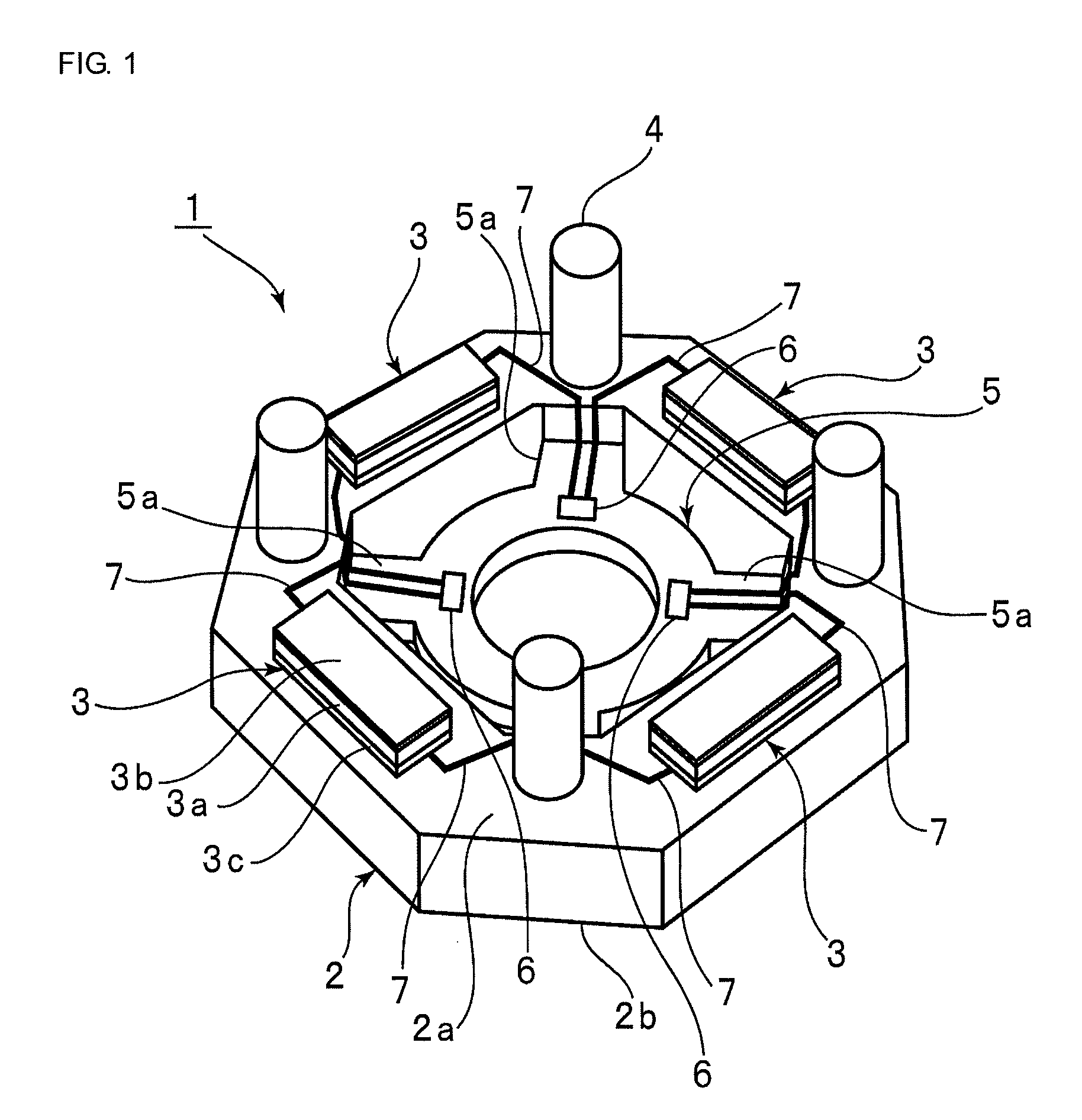
[0023]A piezoelectric motor according to preferred embodiments of the present invention is structured such that a plurality of piezoelectric elements are arranged on a surface of a stator body or on another surface of the stator body opposite the surface, an electrode wiring plate is integrated with the stator body, the plurality of piezoelectric elements are electrically connected a plurality of electrodes formed on the electrode wiring plate through a plurality of wiring lines constituted by an electroconductive film extending from the surface of the stator body to the electrodes. Therefore, the piezoelectric motor can be manufactured without performing troublesome wiring operations using bonding wires or the like. Moreover, the number of components in assembly can be reduced. Therefore, the piezoelectric motor can be reduced in size and the reliability of the piezoelectric motor can be improved.
[0024]Using the method of manufacturing a piezoelectric motor according to preferred embodiments of the present invention, a stator body of a piezoelectric motor and a stator having a plurality of piezoelectric elements can be obtained only by preparing a mother structure including a mother stator body and a plurality of piezoelectric elements integrated with the mother stator body and cutting the mother structure. Therefore, the piezoelectric motor according to the present invention can be efficiently manufactured.

Problems solved by technology

However, carrying out this forming process is very difficult in reality.
Therefore, problems exist in that troublesome wiring operations have to be performed and a large number of components are required.

Method used


Image

  • Piezoelectric Motor and Method of Manufacturing the Same
  • Piezoelectric Motor and Method of Manufacturing the Same
  • Piezoelectric Motor and Method of Manufacturing the Same

Examples


first embodiment

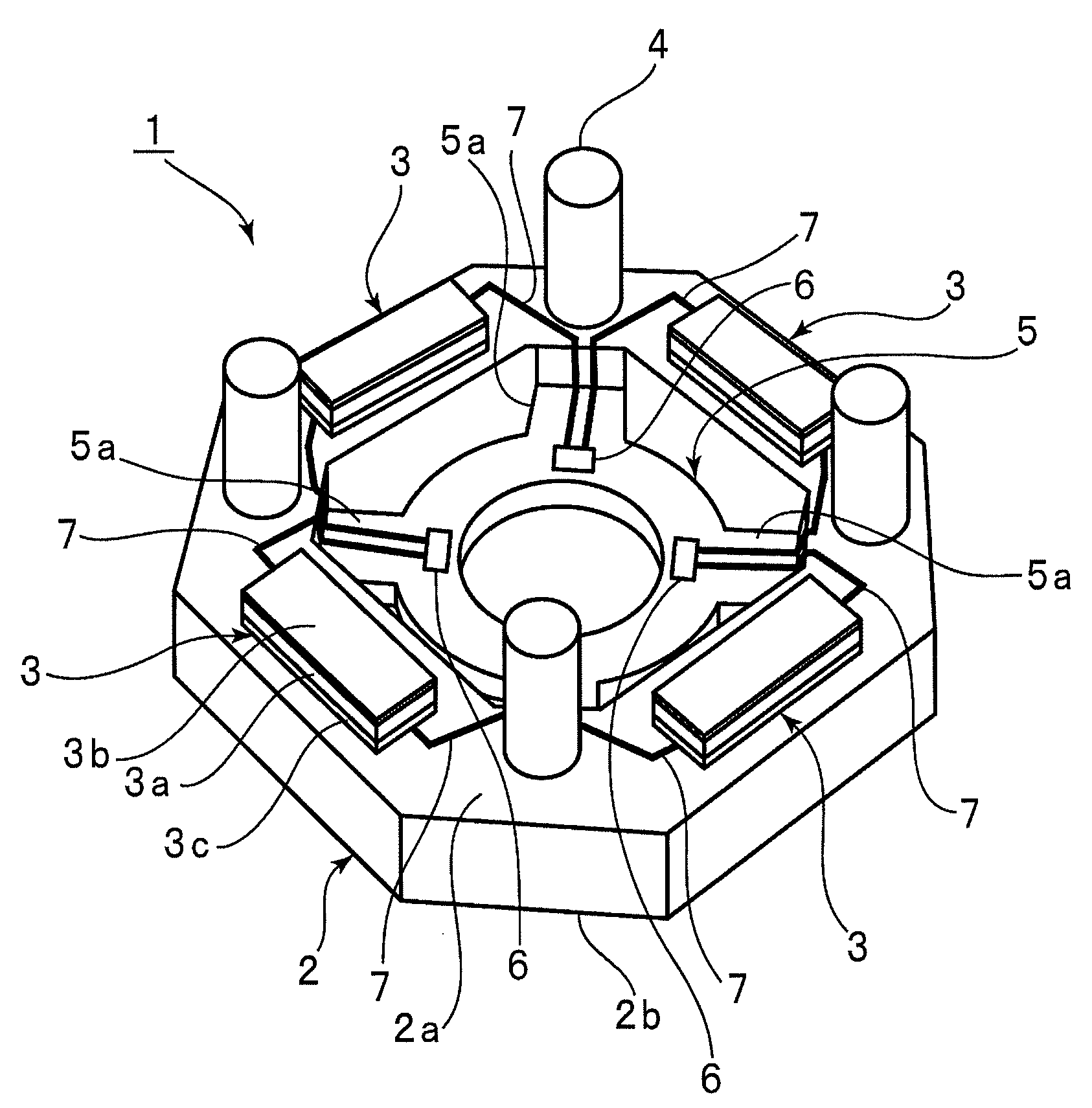
[0040]FIG. 1 is a perspective view showing a stator of a piezoelectric motor according to the present invention.

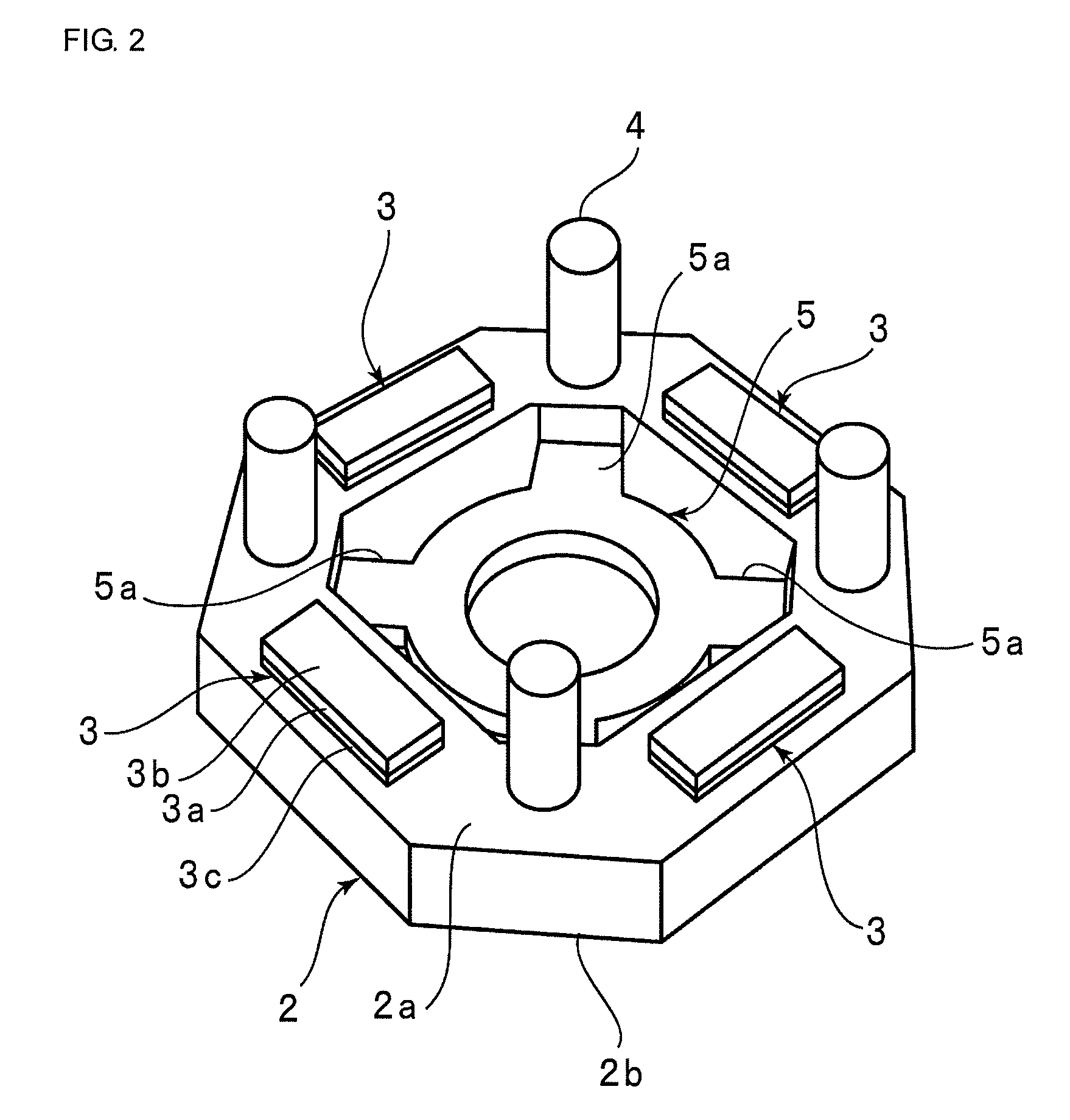
[0041]As shown in FIG. 1, a stator 1 includes a substantially annular stator body 2. The outer periphery and the inner periphery of the substantially annular stator body 2 are substantially octagonal. The stator body 2 includes an upper surface 2a and a lower surface 2b opposite the upper surface 2a. Piezoelectric elements 3 are arranged and fixed on the upper surface 2a in the circumferential direction of the upper surface 2a.

[0042]Each of the piezoelectric elements 3 includes a piezoelectric plate 3a made of a ceramic, a first electrode 3b formed on a first surface of the piezoelectric plate 3a, and a second electrode 3c formed on a second surface opposite the first surface. The piezoelectric plate 3a is made of piezoelectric ceramic. In the embodiment, the piezoelectric plate 3a is polarized in the thickness direction. However, the polarization direction of the piezoel...


PUM

PropertyMeasurementUnit
Thicknessaaaaaaaaaa
Electrical conductoraaaaaaaaaa

Abstract

A piezoelectric motor that includes a rotor and a stator having a surface on which a driving member that is in contact with the rotor for rotating the rotor is disposed. The stator includes a stator body, a plurality of piezoelectric elements disposed on a surface of the stator body, and an electrode wiring plate integrally formed with the stator body. The piezoelectric elements are electrically connected to a plurality of electrodes formed on the electrode wiring plate through a plurality of wiring lines. The wiring lines are constituted by an electroconductive film extending from a surface of the stator body to the electrodes.

Description

BACKGROUND OF THE INVENTION[0001]1. Field of the Invention[0002]The present invention relates to a piezoelectric motor using a plurality of piezoelectric elements. In particular, the present invention relates to a piezoelectric motor in which a stator including a plurality of piezoelectric elements is vibrated so as to drive a rotor in contact with the stator. The present invention further relates to a method of manufacturing the piezoelectric motor.[0003]2. Description of the Related Art[0004]To date, various piezoelectric motors utilizing ultrasonic vibration caused by the piezoelectric effect have been proposed. A piezoelectric motor is also called an ultrasonic motor because a piezoelectric motor uses ultrasonic vibration caused by piezoelectric elements.[0005]For example, Japanese Unexamined Patent Application Publication No. 06-339287 discloses an ultrasonic motor shown in FIG. 12.[0006]An ultrasonic motor 101 shown in FIG. 12 includes a stator 102, and a slider 103 in contact...

Claims


Application Information

Patent Timeline
IPC IPC(8): H02N2/12H02N2/14H01L41/22H01L41/09H02N2/00
CPCH02N2/163Y10T29/42H01L41/25H02N2/22
Inventor FUJIMOTO, KATSUMIASANO, HIROSHI
Owner MURATA MFG CO LTD
Learn More