Eureka AIR delivers breakthrough ideas for toughest innovation challenges, trusted by R&D personnel around the world.

Liquid crystal display and method thereof

Inactive Publication Date: 2010-01-14
SAMSUNG DISPLAY CO LTD
View PDF21 Cites 10 Cited by
  • Summary
  • Abstract
  • Description
  • Claims
  • Application Information

AI Technical Summary

Benefits of technology

[0007]Since a liquid crystal display (“LCD”) is a passive self-luminous device, and requires a light source such as a backlight assembly, there are technical difficulties and increased costs associated with the LCD. For example, in the case of an edge type backlight assembly, expensive components such as lamp covers and so on, are required to reduce a loss of light emitted from the light source.
[0009]An exemplary embodiment of the present invention provides a liquid crystal display reducing a manufacturing cost and an inflow of foreign substances thereto.

Problems solved by technology

Since a liquid crystal display (“LCD”) is a passive self-luminous device, and requires a light source such as a backlight assembly, there are technical difficulties and increased costs associated with the LCD.
For example, in the case of an edge type backlight assembly, expensive components such as lamp covers and so on, are required to reduce a loss of light emitted from the light source.
However, as the structure of the lower receptacle and so on is changed, it may be difficult to manufacture or assemble other components, or foreign substances may flow into the liquid crystal display due to gaps between the components.

Method used


Image

  • Liquid crystal display and method thereof
  • Liquid crystal display and method thereof
  • Liquid crystal display and method thereof

Examples


Embodiment Construction

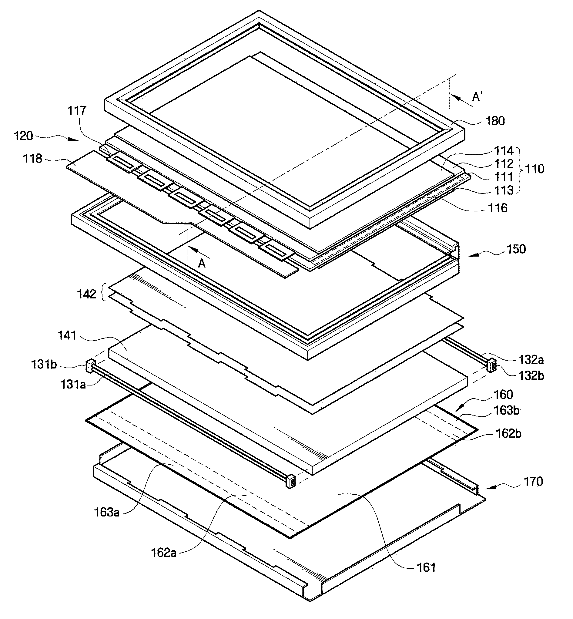
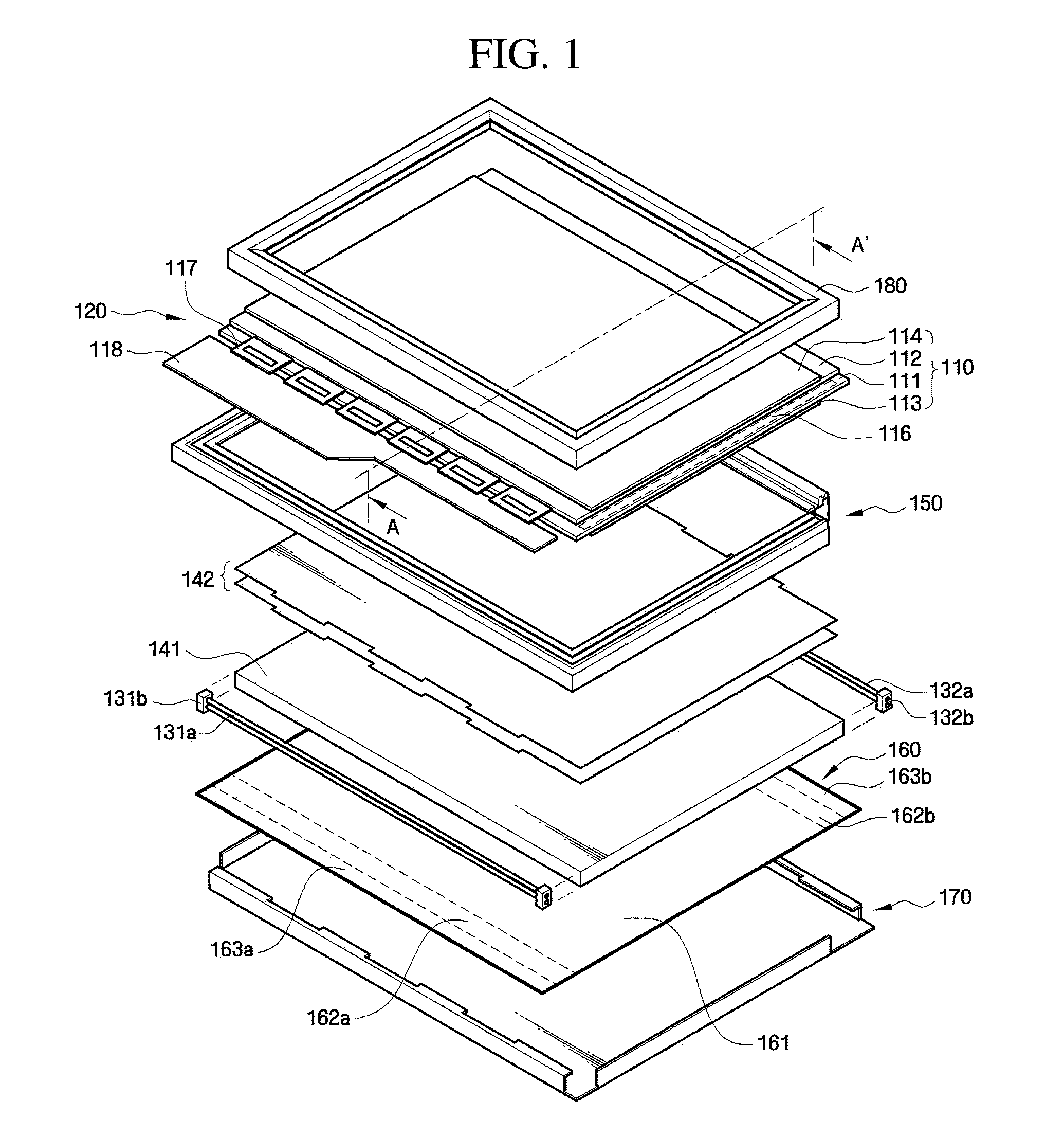
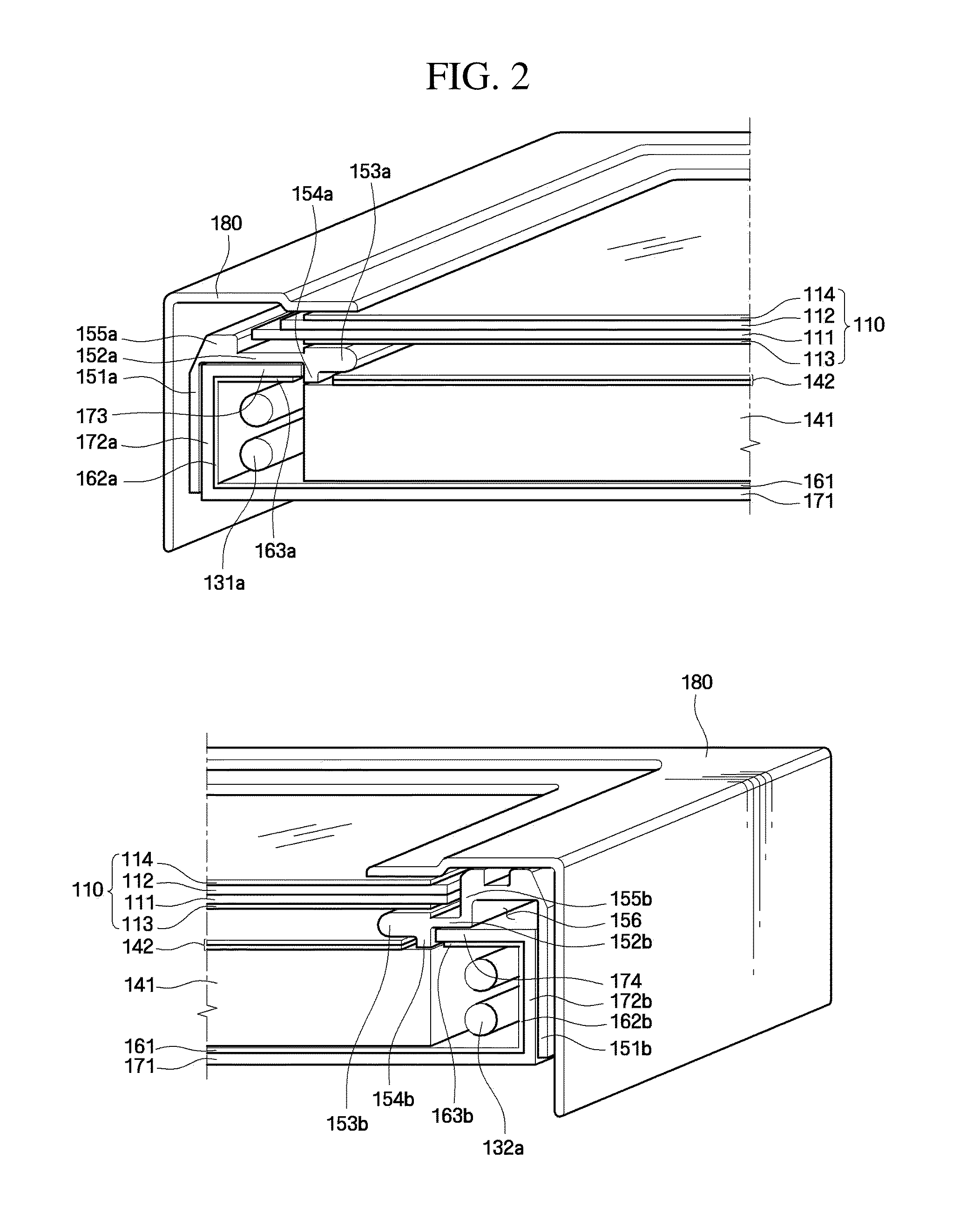
[0026]Hereinafter, exemplary embodiments of the present invention will be described in detail with reference to the accompanying drawings. The aspects and features of the present invention and methods for achieving the aspects and features will be apparent by referring to the embodiments to be described in detail with reference to the accompanying drawings. However, the present invention is not limited to the embodiments disclosed hereinafter, but can be implemented in diverse forms. The matters defined in the description, such as the detailed construction and elements, are nothing but specific details provided to assist those of ordinary skill in the art in a comprehensive understanding of the invention, and the present invention is only defined within the scope of the appended claims. In the entire description of the present invention, the same drawing reference numerals are used for the same elements across various figures. In the drawings, the size and relative sizes of layers a...


PUM


Abstract

A liquid crystal display includes a light guide plate guiding light, light sources disposed adjacent to at least one side of the light guide plate, and a lower receptacle. The lower receptacle includes a bottom plate on which the light guide plate and the light sources are disposed, a lower receptacle side wall extending in a direction substantially perpendicular to the bottom plate and from an edge of the bottom plate, and an upper plate extended from the lower receptacle side wall and substantially parallel to the bottom plate. The upper plate does not overlap the light guide plate in a plan view of the liquid crystal display.

Description

[0001]This application claims priority to Korean Patent Application No. 10-2008-0068196, filed on Jul. 14, 2008, and all the benefits accruing therefrom under 35 U.S.C. §119, the contents of which are incorporated herein in its entirety by reference.BACKGROUND OF THE INVENTION[0002]1. Field of the Invention[0003]The present invention relates to a liquid crystal display, and more particularly to a liquid crystal display that can reduce a manufacturing cost and an inflow of foreign substances.[0004]2. Description of the Related Art[0005]A liquid crystal display (“LCD”), which is one of the most widely used types of flat panel displays (“FPDs”), includes two substrates, on which electrodes are formed, and a liquid crystal layer interposed between the two substrates. In such a liquid crystal display, liquid crystal molecules of the liquid crystal layer are aligned or disposed in accordance with voltages being applied to the electrodes, and thus the quantity of light passing through the ...

Claims


Application Information

Patent Timeline
IPC IPC(8): G02F1/1333H01J9/24
CPCG02B6/0088G02F2001/133317G02F1/133308G02F1/133317G02F1/1333G02F1/1335
Inventor LEE, JEOUNG-GWEN
Owner SAMSUNG DISPLAY CO LTD
Why Eureka
Eureka Blog
Learn More