Heat-dissipating device and projection display apparatus having the same

a technology of heat dissipation device and projection display device, which is applied in the direction of lighting and heating apparatus, instruments, projectors, etc., can solve the problems of reducing the operation life and projection performance, affecting the operation efficiency of the device, and causing a lot of noise, etc., to achieve the effect of simplifying the operation

Inactive Publication Date: 2010-01-14
CORETRONIC
View PDF12 Cites 16 Cited by
  • Summary
  • Abstract
  • Description
  • Claims
  • Application Information

AI Technical Summary

Benefits of technology

[0006]The invention provides a heat-dissipating device used in a projection display apparatu

Problems solved by technology

However, since the size of an opening formed between two adjacent immobile guiding plates 108 is not adjustable, containments such as dust are liable to enter the inside of the projection display apparatus to

Method used


Image

  • Heat-dissipating device and projection display apparatus having the same
  • Heat-dissipating device and projection display apparatus having the same
  • Heat-dissipating device and projection display apparatus having the same

Examples


Embodiment Construction

[0019]In the following detailed description of the preferred embodiments, reference is made to the accompanying drawings which form a part hereof, and in which are shown by way of illustration specific embodiments in which the invention may be practiced. In this regard, directional terminology, such as “top,”“bottom,”“front,”“back,” etc., is used with reference to the orientation of the Figure(s) being described. The components of the present invention can be positioned in a number of different orientations. As such, the directional terminology is used for purposes of illustration and is in no way limiting. On the other hand, the drawings are only schematic and the sizes of components may be exaggerated for clarity. It is to be understood that other embodiments may be utilized and structural changes may be made without departing from the scope of the present invention. Also, it is to be understood that the phraseology and terminology used herein are for the purpose of description an...


PUM


Abstract

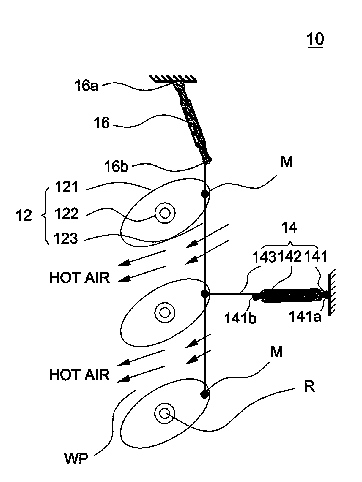
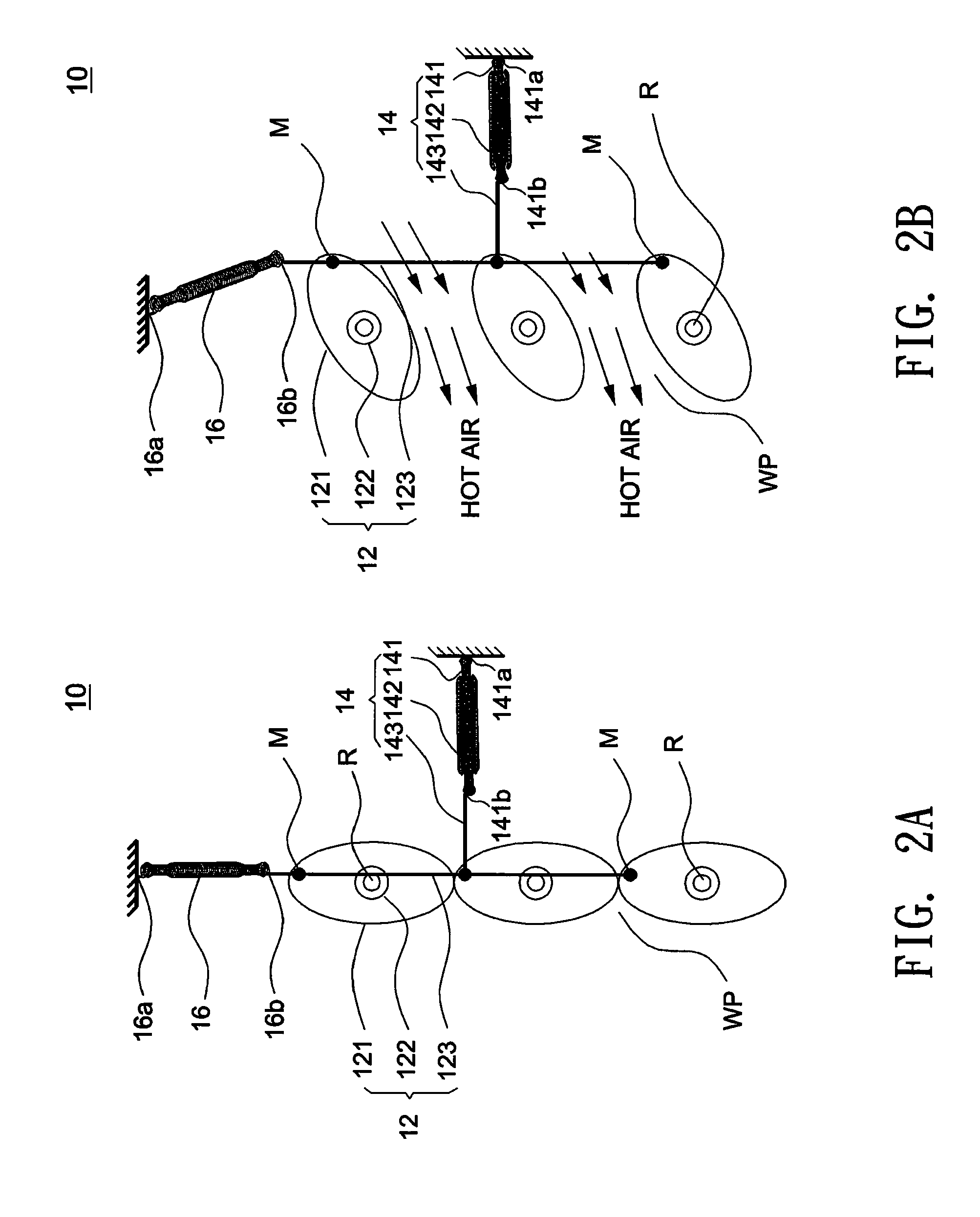
A heat-dissipating device used in a projection display apparatus with an air outlet includes a fence module, at least one resilient member, and a shape memory alloy module. The fence module is disposed at the air outlet and includes at least one guiding plate with a pivot. The resilient member exerts a first force on the guiding plate to enable the guiding plate to rotate on the pivot, and the shape memory alloy module deforms when heated to exert a second force on the guiding plate to enable the guiding plate to rotate on the pivot.

Description

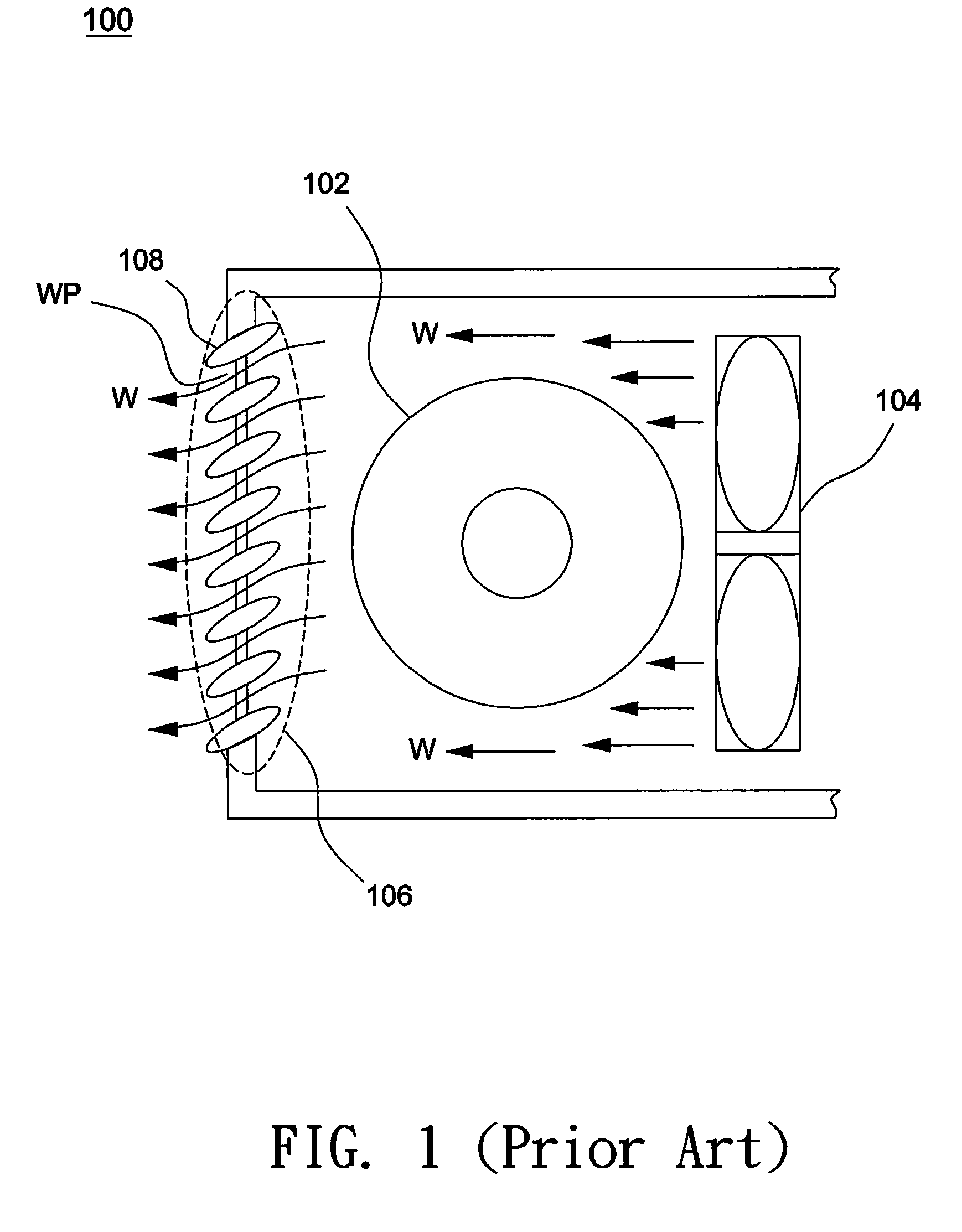
CROSS REFERENCE TO RELATED APPLICATION[0001]This application claims priority of application No. 097126229 filed in Taiwan R.O.C on Jul. 11, 2008 under 35 U.S.C. §119; the entire contents of which are hereby incorporated by reference.BACKGROUND OF THE INVENTION[0002]1. Field of the Invention[0003]The invention relates to a heat-dissipating device, and particularly to a heat-dissipating device adapted to a projection display apparatus with an air outlet.[0004]2. Description of the Related Art[0005]FIG. 1 shows a schematic diagram illustrating a partial structure of a conventional projection display apparatus. Referring to FIG. 1, the projection display apparatus 100 uses a high-power lamp 102 as a light source. Since the high-power lamp 102 generates considerable heat during operation, a fan 104 is disposed near the lamp 102 to induce a forced convection of air, and the flow W flows through the lamp 102 and leaves by an air outlet WP to cool down the lamp 102. As shown in FIG. 1, a fi...

Claims


Application Information

Patent Timeline
IPC IPC(8): G03B21/16
CPCG03B21/16
Inventor CHIEN, CHAO-NANLO, WEI-CHENGHSU, NIEN-HUI
Owner CORETRONIC
Why Eureka
Try Eureka