Magnetic head assembly and magnetic recording apparatus

a magnetic recording and head assembly technology, applied in special recording techniques, instruments, record information storage, etc., can solve the problems of slowing down the speed of the increase of recording density, difficult to realize such high recording density, and difficult to efficiently apply high-frequency magnetic field to the medium

Inactive Publication Date: 2010-01-14
KK TOSHIBA
View PDF5 Cites 57 Cited by
  • Summary
  • Abstract
  • Description
  • Claims
  • Application Information

AI Technical Summary

Problems solved by technology

However, in the 2000s, the problem of thermal fluctuation of the magnetic recording media has been actualized and therefore the speed of the increase of the recording density has temporarily slowed down.
However, it is thought that realization of such high recording density is not easy even by using the perpendicular magnetic recording scheme because the problem of thermal fluctuation is actualized again.
However, in the technique disclosed in the Patent document 1, the high-freq...

Method used


Image

  • Magnetic head assembly and magnetic recording apparatus
  • Magnetic head assembly and magnetic recording apparatus
  • Magnetic head assembly and magnetic recording apparatus

Examples


first embodiment

[0048]A magnetic recording head according to a first embodiment of the invention will be described with assuming the case of recording on a multiparticle medium for perpendicular magnetic recording.

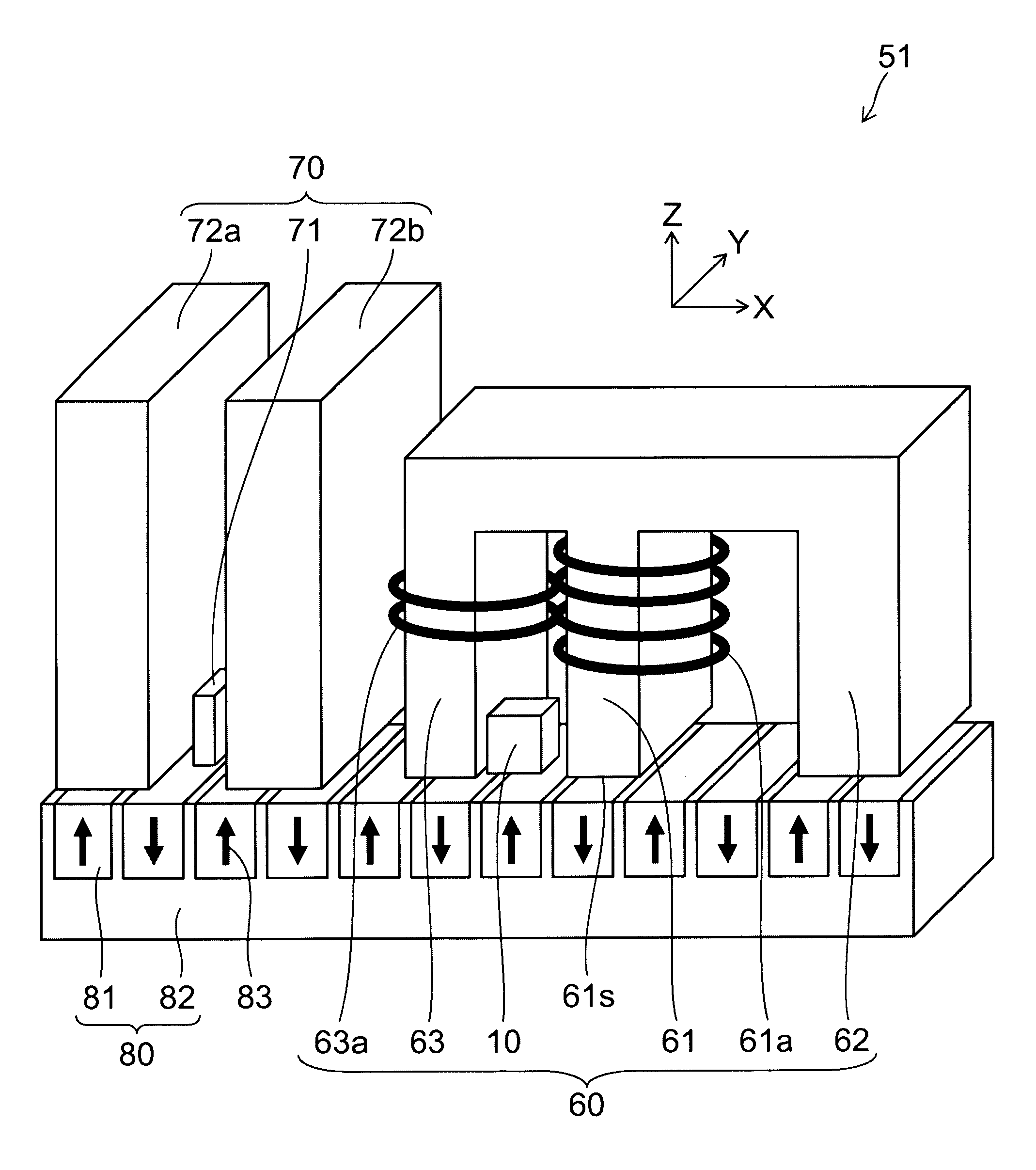
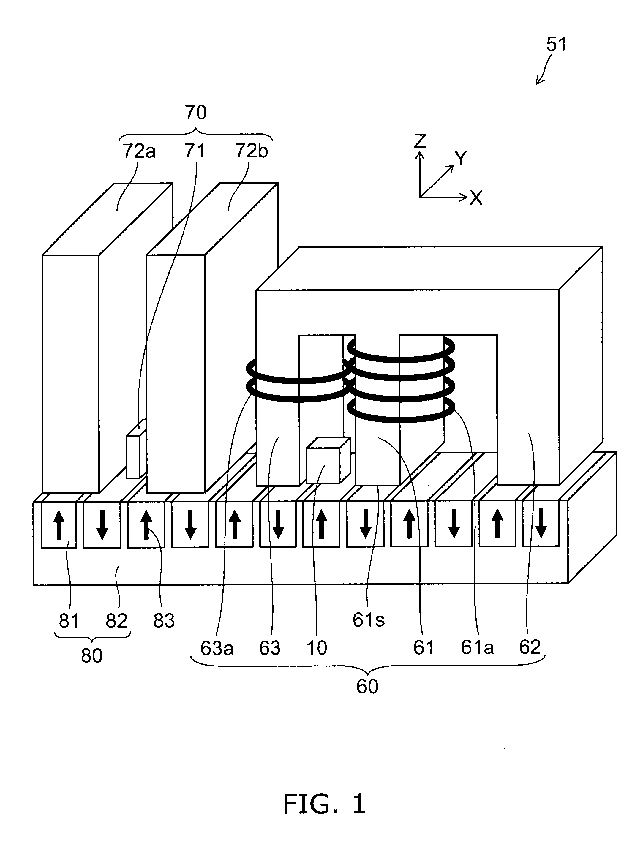
[0049]FIG. 1 is a schematic perspective view illustrating the configuration of the magnetic recording head according to the first embodiment of the invention.

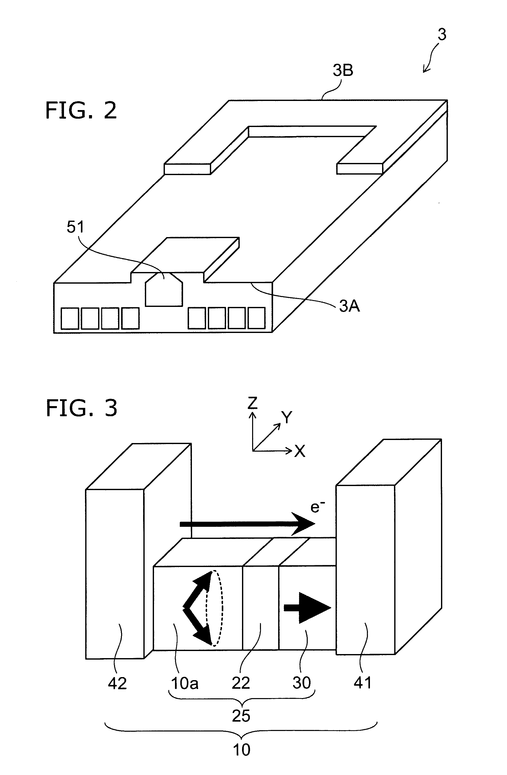
[0050]FIG. 2 is a schematic perspective view illustrating the structure of a head slider on which the magnetic recording head according to the first embodiment of the invention is mounted.

[0051]FIG. 3 is a schematic perspective view illustrating the structure of a spin torque oscillator used in the magnetic recording head according to the first embodiment of the invention.

[0052]FIG. 4 is a schematic perspective view illustrating the structure of a relevant part of the magnetic recording head according to the first embodiment of the invention.

[0053]As shown in FIG. 1, the magnetic recording head 51 according to the first embodiment of...

second embodiment

[0112]FIG. 7 is a schematic perspective view illustrating the structure of a relevant part of the magnetic head according to a second embodiment of the invention.

[0113]As shown in FIG. 7, in the writing head section 60 used in the magnetic recording head 52 according to the second embodiment of the invention, a current can be supplied to the main magnetic pole coil 61a independently of the adjustment magnetic pole coil 63a.

[0114]That is, the magnetic recording head 52 according to this embodiment has the main magnetic pole 61 for applying a recording magnetic field to the magnetic recording medium 80, the adjustment magnetic pole 63 provided in the vicinity of the main magnetic pole 61, the spin torque oscillator 10, the main magnetic pole coil 61a for magnetizing the main magnetic pole 61, and the adjustment magnetic pole coil 63a for magnetizing the adjustment magnetic pole 63. At least part of the spin torque oscillator 10 is provided between the main magnetic pole 61 and the ad...

third embodiment

[0157]FIG. 13 is a schematic perspective view illustrating the structure of a relevant part of the magnetic recording head according to a third embodiment of the invention.

[0158]As shown in FIG. 13, in the magnetic recording head 53 according to the third embodiment of the invention, the relative positions of the main magnetic pole 61 and the adjustment magnetic pole 63 in the writing head section 60 are reversed, compared to the magnetic recording head 51 illustrated in FIG. 1. That is, the main magnetic pole 61 is disposed at the far position from the return path 62 of the writing head section 60, and the adjustment magnetic pole 63 is provided between the main magnetic pole 61 and the return path 62. Other than this, the magnetic recording head 53 is the same as the magnetic recording head 51. That is, the spin torque oscillator 10 is disposed between the main magnetic pole 61 and the adjustment magnetic pole 63, and the reproducing head section 70 is disposed on the opposite sid...


PUM


Abstract

A magnetic head assembly includes a magnetic recording head, a head slider, a suspension and an actuator arm. The magnetic recording head includes: a main magnetic pole; an adjustment magnetic pole provided together with the main magnetic pole; a spin torque oscillator; a main magnetic pole coil being wound around the main magnetic pole; and an adjustment magnetic pole coil being wound around the adjustment magnetic pole. At least part of the spin torque oscillator is provided between the main magnetic pole and the adjustment magnetic pole. A way of winding of the adjustment magnetic pole coil is different from a way of winding of the main magnetic pole coil. The magnetic recording head is mounted on the head slider. The head slider is mounted on one end of the suspension. The actuator arm is connected to the other end of the suspension.

Description

CROSS-REFERENCE TO RELATED APPLICATIONS[0001]This application is based upon and claims the benefit of priority from the prior Japanese Patent Application No.2008-181911, filed on Jul. 11, 2008; the entire contents of which are incorporated herein by reference.BACKGROUND OF THE INVENTION[0002]This invention relates to a magnetic head assembly and a magnetic recording apparatus.BACKGROUND ART[0003]In the 1990s, practical application of MR (Magneto-Resistive effect) head and GMR (Giant Magneto-Resistive effect) head has acted as a trigger and recording density and recording capacity of HDD (Hard Disk Drive) have drastically increased. However, in the 2000s, the problem of thermal fluctuation of the magnetic recording media has been actualized and therefore the speed of the increase of the recording density has temporarily slowed down. Even so, it has played a leading role that perpendicular magnetic recording, which is fundamentally more advantageous than the longitudinal magnetic reco...

Claims


Application Information

Patent Timeline
IPC IPC(8): G11B5/48
CPCG11B5/02G11B5/1278G11B2005/0024G11B5/3146G11B2005/0005G11B5/314
Inventor YAMADA, KENICHIROIWASAKI, HITOSHITAKAGISHI, MASAYUKIFUNAYAMA, TOMOMITAKASHITA, MASAHIROSHIMIZU, MARIKOOIKAWA, SOICHIKOUI, KATSUHIKO
Owner KK TOSHIBA
Why Eureka
Try Eureka