Clip and backlight assembly

a backlight assembly and clip technology, applied in the direction of snap fasteners, lighting and heating apparatus, instruments, etc., can solve the problems of reducing operation efficiency, difficult operations, and reducing the type of fixing member, so as to improve working efficiency and thin the overall structure

Inactive Publication Date: 2010-01-14
SONY CORP
View PDF4 Cites 37 Cited by
  • Summary
  • Abstract
  • Description
  • Claims
  • Application Information

AI Technical Summary

Benefits of technology

[0008]To address this, the present invention provides a new and improved clip and backlight assembly that both improve workability and allow the overall structure to be made thinner.
[0010]With this structure, when the insert portion of the clip is inserted into the insertion hole of the chassis, the insert portion engages with the chassis. Then, the at least one light emitting board is sandwiched between the collar portion of the clip and the chassis, and the light emitting board is clamped in place by the collar portion and the chassis. As a result, the light emitting board can be held in place with an appropriate pressure by the clip. In this case, the clip can fix the light emitting board in place simply by inserting the insert portion into the insertion hole. Further, the thickness of the collar portion is set to be equal to or less than the amount of protrusion of the light emitting portion formed protrudingly from the light emitting board, and therefore, at the time of assembly, the light emitting portion is either the same height as the collar portion of the clip, or protrudes further than the collar portion. As a consequence, the light emitted from the light emitting portion is not obstructed by the collar portion.
[0019]According to the embodiments of the present invention described above, working efficiency can be improved and the overall structure can be made thinner.

Problems solved by technology

This type of fixing member is often an obstacle to achieving a backlight assembly with a lower profile.
However, when adhesive members and the like are used, it is difficult to remove each of the components, and sometimes operation efficiency is reduced, operations are more difficult and workability also deteriorates.
Clips have been developed, such as the fixing members disclosed in the above-mentioned JP-A-2003-278723, JP-A-2006-183772 and JP-A-2008-71586, but they do not sufficiently fulfill the above-described requirements.

Method used


Image

  • Clip and backlight assembly
  • Clip and backlight assembly
  • Clip and backlight assembly

Examples


Embodiment Construction

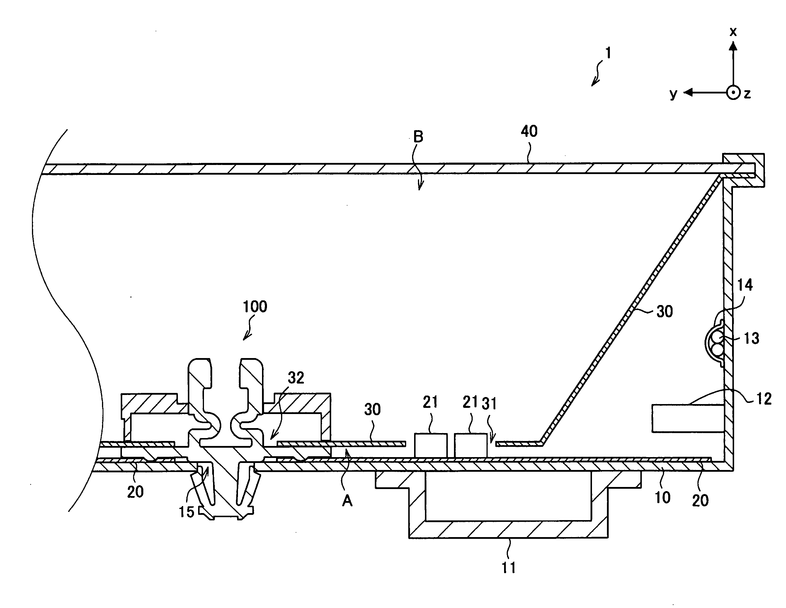
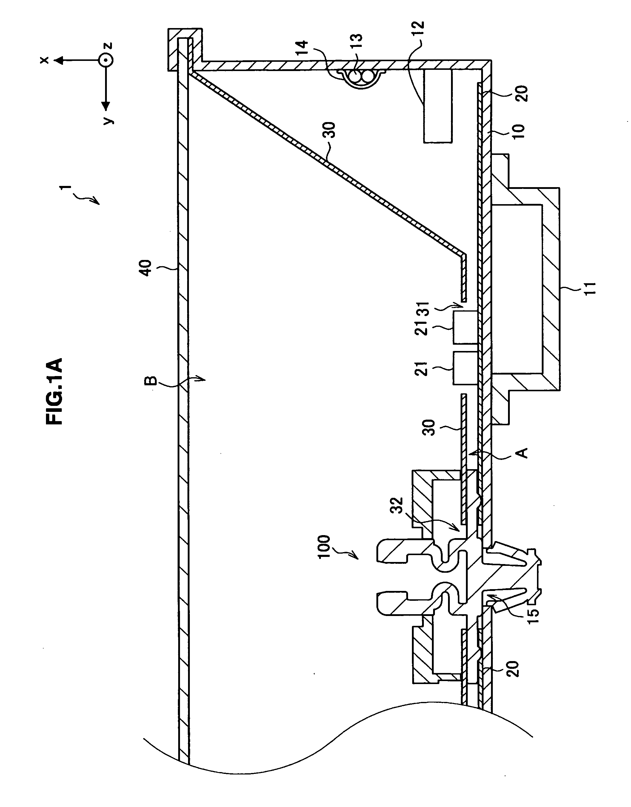
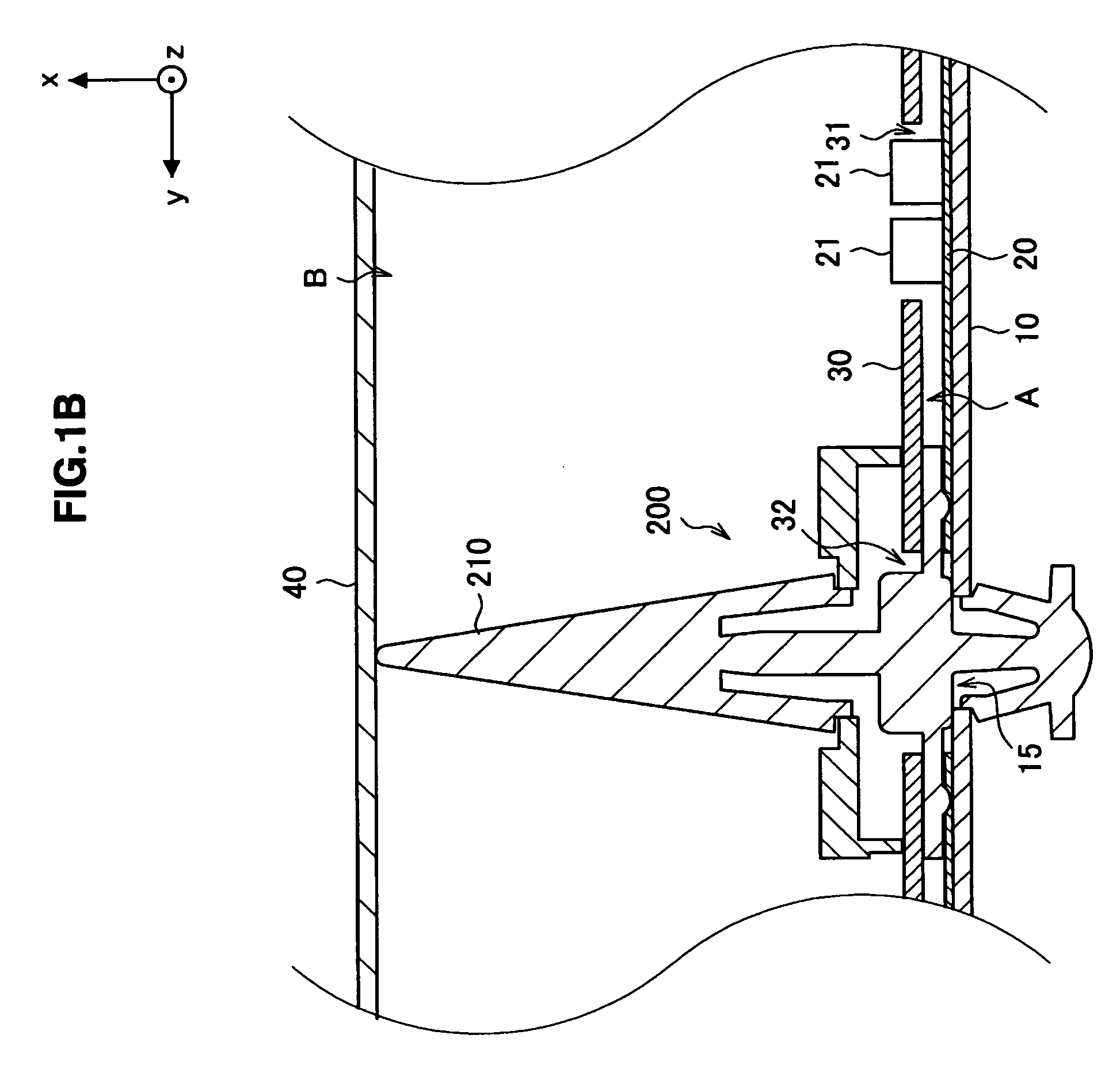
[0030]Hereinafter, preferred embodiments of the present invention will be described in detail with reference to the appended drawings. Note that, in this specification and the appended drawings, structural elements that have substantially the same function and structure are denoted with the same reference numerals, and repeated explanation of these structural elements is omitted.

[0031]Each embodiment of the present invention explained below relates to a clip and a backlight assembly that uses the clip. The clip has a special structure that allows not only improved working efficiency but also, when used in the backlight assembly, contributes significantly to making the backlight assembly thinner. The clip can achieve various other effects than the type of effects described here above, and these effects will be explained in detail below. To make each of the embodiments of the present invention easy to understand, before an explanation of the clip, the backlight assembly according to e...


PUM


Abstract

A clip provided by the present invention includes an insert portion that is inserted into an insertion hole formed in a flat-shaped chassis and that engages with the chassis, and a collar portion that is formed in a flat shape around the circumference of the insert portion. When the insert portion is inserted into the insertion hole, the collar portion and the chassis clamp at least one light emitting board that is positioned in contact with the chassis, and the thickness of the collar portion is set to be equal to or less than an amount of protrusion of a light emitting portion formed protrudingly from the light emitting board.

Description

[0001]The present application claims priority from Japanese Patent Application No. JP 2008-159640 filed in the Japanese Patent Office on Jun. 18, 2008, the entire content of which is incorporated herein by reference.BACKGROUND OF THE INVENTION[0002]1. Field of the Invention[0003]The present invention relates to a clip and a backlight assembly.[0004]2. Description of the Related Art[0005]Flat type image display devices have been developed in recent years, and the display devices are being made increasingly thinner. Of these, display devices such as liquid crystal display devices, for example, are equipped with a backlight assembly in addition to a liquid crystal panel that forms the image. The backlight assembly has, for example, a light emitting board on which are positioned light emitting portions such as LED or FL tubes and the like, and in the case of a liquid crystal display device, the light emitting board emits a predetermined light towards the liquid crystal panel. The image ...

Claims


Application Information

Patent Timeline
Patent Type & Authority Applications(United States)
IPC IPC(8): G09F13/04A44B21/00
CPCF16B5/065Y10T24/44017G02F1/133608
Inventor MORO, SHUUJISUZUKI, YUICHITAKATSUKA, HIROSHIIDE, EIJISHIBATA, HIROKAZU
Owner SONY CORP
Why Eureka
Try Eureka