
Microphone unit for stereophonic recording

a stereophonic recording and microphone technology, applied in the direction of stereophonic arrangments, transducer types, piezoelectric/electrostrictive transducers, etc., can solve the problems of strength and weight, difficult to adjust the position of the microphone, directivity and sound quality degradation, etc., to eliminate or suppress to minimum the influence

Active Publication Date: 2010-01-14
ZOOM
View PDF1 Cites 21 Cited by
  • Summary
  • Abstract
  • Description
  • Claims
  • Application Information

AI Technical Summary

Benefits of technology

[0009]It is therefore an object of the present invention to provide a microphone unit for stereophonic recording, in which it is possible to adjust an intersecting angle of sound collecting axes in accordance with conditions without impairing the directivity and sound quality of microphones.
[0010]It is another object of the present invention to provide a microphone unit for stereophonic recording, in which it is possible to easily adjust an intersecting angle of sound collecting axes.
[0011]It is still another object of the present invention to provide a microphone unit for stereophonic recording, in which it is possible to adjust an intersecting angle of sound collecting axes within a practical and preferred range.

Problems solved by technology

The unidirectional microphone largely suffers influences of an area of a rear opening and a shape of an obstacle in the rear opening direction, and hence the directivity and sound quality degrade in the above-mentioned structure.
In the microphone unit disclosed in Japanese Patent Application Laid-open No. 2007-43510, too, a scale of the structure for moving the moving bases is large, thereby causing problems of the strength and weight thereof, and in addition, it is difficult to adjust the positions of the microphones because the moving bases may be freely moved within a certain range.
Further, because routing distances of signal lines connected to the microphones become larger, there was liable to cause a breakage of the lines.

Method used


Image

  • Microphone unit for stereophonic recording
  • Microphone unit for stereophonic recording
  • Microphone unit for stereophonic recording

Examples


Embodiment Construction

[0036]Hereinafter, description is made of an embodiment of the present invention. It should be noted that the following description is made for understanding the invention more deeply, but is not intended to limit the scope of the present invention.

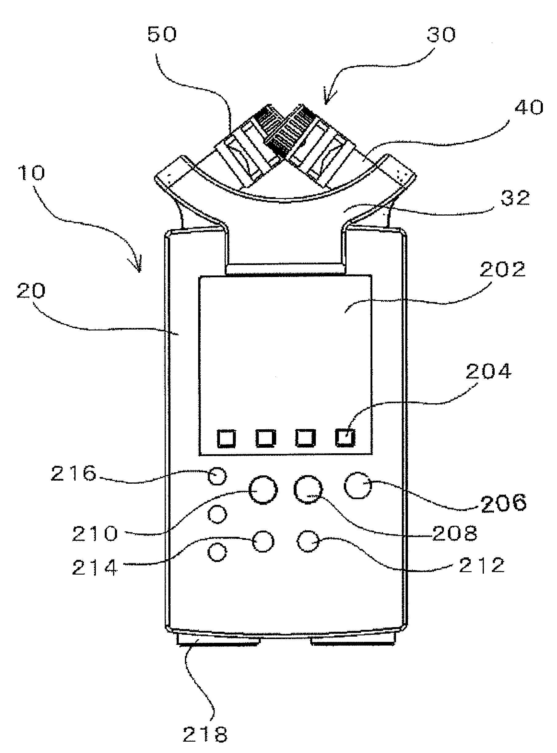
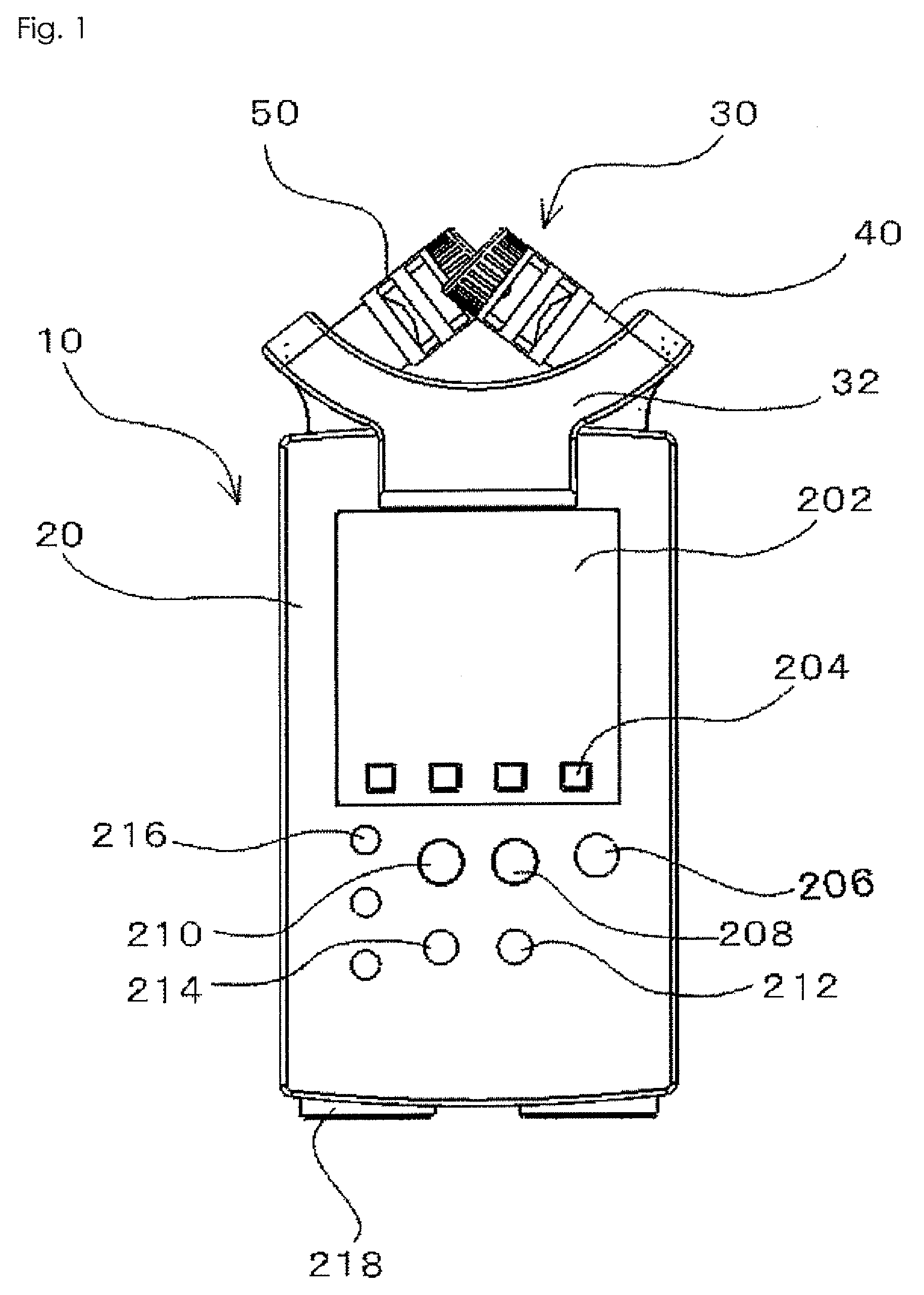
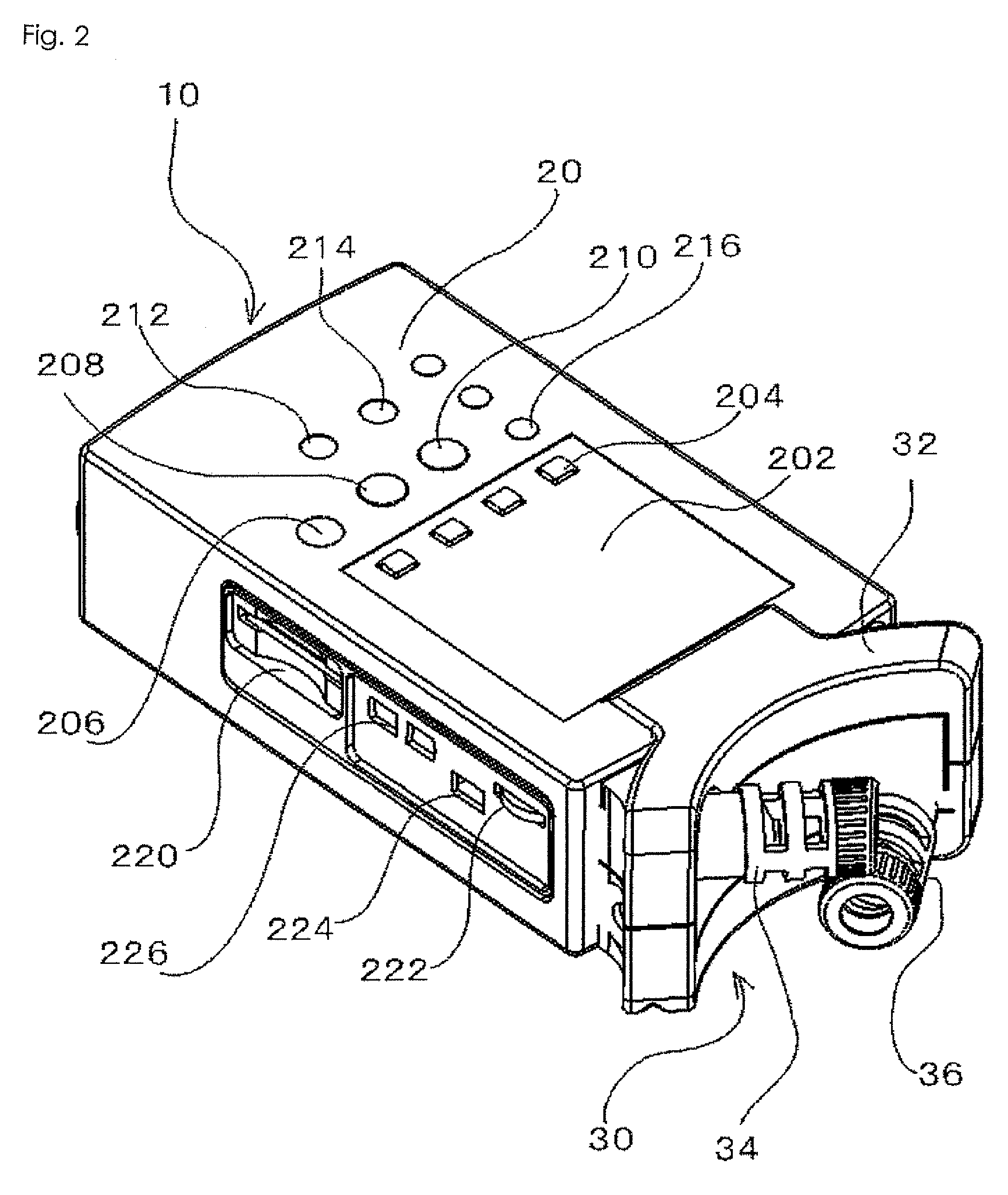
[0037]FIGS. 1 and 2 each are a front view and a perspective view of a portable sound recorder to which a microphone unit for stereophonic recording according to an embodiment of the present invention is applied.

[0038]In each of FIGS. 1 and 2, a portable sound recorder 10 includes a main body 20 having a rectangular shape, and a microphone unit 30 which is provided and projected from a front end of the main body 20.

[0039]Provided on a top surface of the main body 20 is a liquid crystal display 202 for indicating a current status of the portable sound recorder 10, such as a recording time, a recording level, and a battery remaining amount. Behind the liquid crystal display 202, there are provided four track selection keys 204 for selecting ...


PUM


Abstract

To provide a microphone unit for stereophonic recording capable of adjusting an intersecting angle of sound collecting axes in accordance with conditions without impairing directivity and sound quality of the microphone. Respective rotation bases (408, 508) are rotatable about a center axis with respect to mounting bases (404, 504), respectively, which are mounted to a main body (20) of a portable sound recorder (10) through respective brackets (402, 502). Respective top ends of respective knurls (414, 514) of leading ends of the respective rotation bases (408, 508) has a shape being cut to form an inclined surface from a radial direction, and respective microphones (418, 518) are retained so that diaphragms (420, 520) are in consonance with the cut surface. Accordingly, by rotation of the respective rotation bases (408, 508), sound collecting axes (426, 526) vertically extending from the diaphragms (420, 520) are changed in their axes like a precession, thereby being capable of adjusting an intersecting angle of the sound collecting axes (426, 526) of right and left microphones (418, 518).

Description

BACKGROUND OF THE INVENTION[0001]1. Field of the Invention[0002]The present invention relates to a microphone unit for stereophonic recording in which a pair of right and left unidirectional microphones are arranged so that respective recording axes of the pair of microphones are substantially intersected, and more particularly, to a microphone unit for stereophonic recording capable of adjusting a intersected angle of the recording axes in accordance with circumstances without deteriorating directivity and sound quality of the microphone.[0003]2. Description of the Related Art[0004]Several methods are in practical use as a stereophonic recording method, and an XY type is generally used because of being most general and reliable method. The XY type is a method of collecting sound by arranging a pair of right and left unidirectional microphones in an inverted V-shape so that respective recording axes of the pair of microphones are intersected. The sound collecting axis is a virtual a...

Claims


Application Information

Patent Timeline
Patent Type & Authority Applications(United States)
IPC IPC(8): H04R5/00
CPCH04R5/027
Inventor KAWANO, TATSUYA
Owner ZOOM
Learn More