Construction vehicle

a construction vehicle and vehicle body technology, applied in the direction of tractors, fluid gearings, gearings, etc., can solve the problems of reducing traction force, reducing operability, vehicle stopping, etc., to suppress the reduction of traction force, reduce the upper limit of engine speed, and inhibit slippage

Active Publication Date: 2010-01-14
KOMATSU LTD
View PDF24 Cites 29 Cited by
  • Summary
  • Abstract
  • Description
  • Claims
  • Application Information

AI Technical Summary

Benefits of technology

[0014]In this construction vehicle, it is possible to ensure that the maximum traction force is achieved at a lower vehicle speed, by reducing the upper limit of the engine speed as the vehicle speed decreases during the slip reduction control. It is thereby possible to inhibit slipping during work on roads of low friction. Since there is a limit to reducing the upper limit of the engine speed even in cases in which the slip reduction control is performed, there is also a limit to reducing the vehicle speed at which the maximum traction force is achieved. Specifically, the maximum traction force is achieved at a certain vehicle speed, and there is a tendency for the traction force to decrease at this vehicle speed or lower even if the slip reduction control is implemented. Therefore, it is possible to further suppress reductions in traction force during low-speed travel by performing the slip reduction control together with the control for increasing the maximum displacement of the travel hydraulic motor as the vehicle speed decreases, and setting the maximum displacement to the limit value or greater.

Problems solved by technology

Therefore, in cases in which work is performed for pushing earth or the like at low speeds, such as excavation, the traction force decreases when the speed of the vehicle decreases to a certain speed, and there is a possibility of operability decreasing or of the vehicle stopping.

Method used


Image

  • Construction vehicle
  • Construction vehicle
  • Construction vehicle

Examples


Embodiment Construction

Overall Configuration

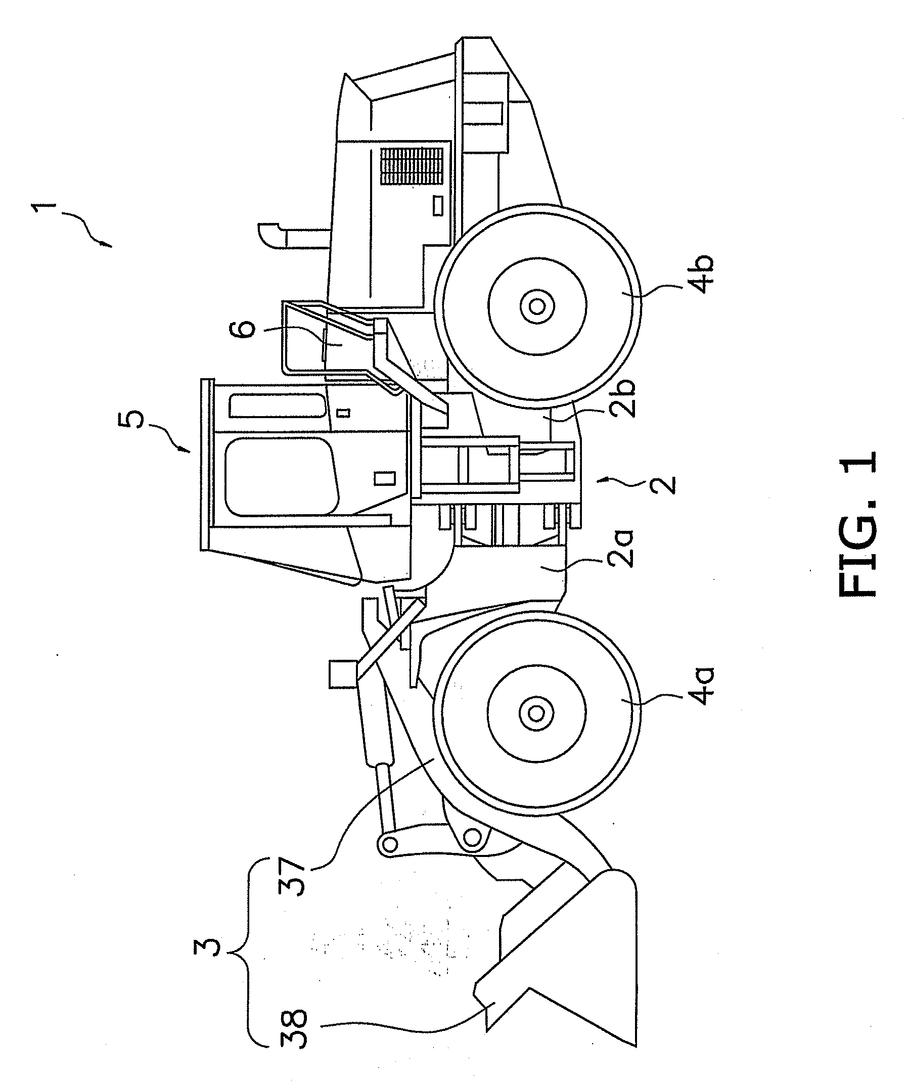
[0023]A side view of a construction vehicle 1 according to an embodiment of the present invention is shown in FIG. 1. The construction vehicle 1 is a wheel loader capable of self-propulsion by means of tires 4a, 4b, and also capable of using a work device 3 to perform desired work. The construction vehicle 1 comprises a vehicle frame 2, a work device 3, tires 4a, 4b, and a driver cabin 5.

[0024]The vehicle frame 2 has a front frame 2a disposed on the front side and a rear frame 2b disposed on the rear side, and the front frame 2a and rear frame 2b are coupled in the center of the vehicle frame 2 and are capable of swinging to the left and right.

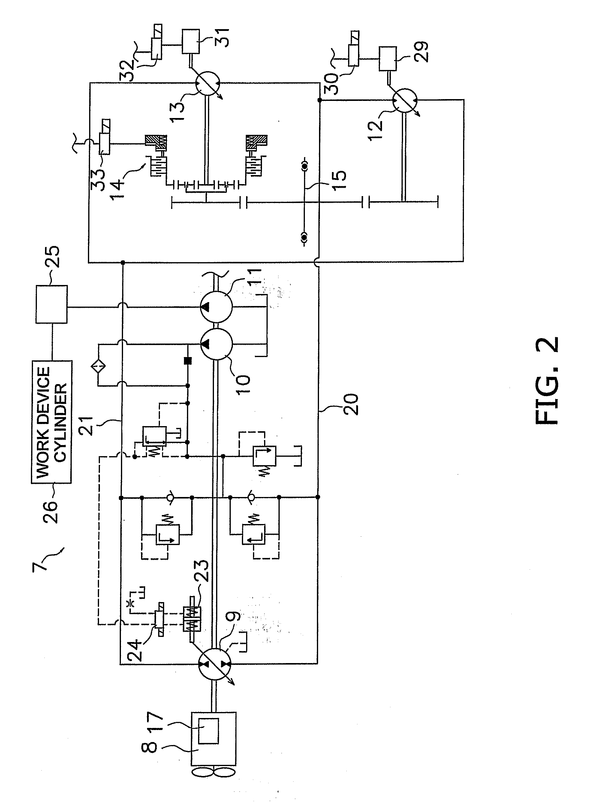
[0025]The work device 3 and a pair of front tires 4a are attached to the front frame 2a. The work device 3 is a device driven by pressure oil from a work device hydraulic pump 11 (see FIG. 2), and the work device has lift arms 37 mounted to the front part of the front frame 2a, a bucket 38 attached to the distal ends of th...


PUM


Abstract

A construction vehicle includes an engine, a hydraulic pump driven by the engine, a travel hydraulic motor driven by pressure oil discharged from the hydraulic pump, travel wheels driven by the drive force of the travel hydraulic motor, and a controller. The controller is configured to control an engine speed, displacement of the hydraulic pump, and displacement of the travel hydraulic motor in order to control a vehicle speed and the traction force. The controller is further configured to increase a maximum displacement of the travel hydraulic motor as the vehicle speed decreases within a low speed range in which the vehicle speed is equal to or less than a predetermined threshold.

Description

CROSS-REFERENCE TO RELATED APPLICATIONS[0001]This U.S. National stage application claims priority to Japanese Patent Application No. 2006-289668, filed in Japan on Oct. 25, 2006. The entire disclosure of Japanese Patent Application No. 2006-289668 is hereby incorporated herein by reference.TECHNICAL FIELD[0002]The present invention relates to a construction vehicle.BACKGROUND ART[0003]An example of a construction vehicle is one equipped with a so-called HST (Hydrostatic Transmission), wherein a hydraulic pump is driven by an engine and wherein a travel hydraulic motor is driven by pressure oil discharged from the hydraulic pump, thereby causing the vehicle to travel. With this type of construction vehicle, the speed and traction force of the vehicle can be controlled by controlling the engine speed, the displacement of the hydraulic pump, and the displacement of the travel hydraulic motor (Japanese Laid-open Patent Application No. 2004-144254).SUMMARY OF THE INVENTION[0004]Vehicle s...

Claims


Application Information

Patent Timeline
Patent Type & Authority Applications(United States)
IPC IPC(8): F16H61/42B62D49/00F16H59/44F16H61/40F16H61/421F16H61/431
CPCB60W10/06B60W30/188F16H47/02F16H59/44Y10T477/631F16H61/435F16H61/448F16H61/47B60W2710/0644F16H61/421F16H2047/025
Inventor SHIRAO, ATSUSHIWADA, MINORUKUSUMOTO, YUUYA
Owner KOMATSU LTD
Why Eureka
Try Eureka