Method of replacing wind turbine equipment

a technology of wind turbines and equipment, applied in the direction of winding mechanisms, electric generator control, hoisting equipment, etc., can solve the problems of increasing the cost of replacing large equipment and increasing the cost of large equipment replacement, so as to reduce the capacity or capacity required in the reciprocating winch, reduce the cost of replacement operation, and facilitate the effect of replacement operation

Inactive Publication Date: 2010-01-21
MITSUBISHI HEAVY IND LTD
View PDF7 Cites 58 Cited by
  • Summary
  • Abstract
  • Description
  • Claims
  • Application Information

AI Technical Summary

Benefits of technology

[0008]In the above-mentioned Patent Document 1, a crane arm is provided in the nacelle and a winch is disposed on the ground, so that large equipment can be replaced without using large heavy machinery.
[0011]In the above-mentioned Patent Document 2, a movable pulley is provided in the nacelle and a winch is disposed on the ground, so that large equipment can be replaced without using large heavy machinery.
[0013]The present invention has been accomplished for solving the above-mentioned problems, and it is an object thereof to provide a method of replacing wind turbine equipment where the cost necessary for replacing of large equipment in a nacelle can be reduced.
[0016]According to the invention, by changing from the ordinarily-installed winch having a drum for winding a wire to a reciprocating winch not having a drum and by supplying wire that is used for replacing the wind turbine equipment from the drum disposed on the ground, it is possible to use a movable pulley whose usable length of wire is long. With this, the ability or capacity required in the reciprocating winch can be reduced compared with the case where the movable pulley is not used. Therefore, the cost for the replacement operation can be reduced. In addition, since the wind turbine equipment can be replaced without using, for example, large heavy machinery, the replacement operation is easier, resulting in a reduction in the cost for the replacement operation.
[0017]When the wind turbine equipment is replaced, the wire used for replacing of the wind turbine equipment is hoisted from the drum disposed on the ground. Therefore, it is not necessary to ensure a space for disposing the drum in the nacelle. In particular, since the length of the wire necessary for using the movable pulley is long, the size of the drum for winding the wire tends to be large. Even in such a case, the nacelle can be prevented from increasing in size by disposing the drum on the ground. Consequently, the cost for replacing the wind turbine equipment can be reduced.
[0018]According to the method of replacing the wind turbine equipment of the present invention, the ordinarily-installed winch having a wire wound drum is replaced by a reciprocating winch not having a drum, and also the wire that is used for replacing the wind turbine equipment is supplied from the drum disposed on the ground. Consequently, an advantage is afforded in that the cost of replacing the wind turbine equipment, which is the large equipment in the nacelle, can be reduced.

Problems solved by technology

Therefore, this technique has the problem that the cost for replacing large equipment is increased.
In addition, since the winch used has a large capacity capable of hoisting and suspending the large equipment, this technique has the problem that the cost for replacing the large equipment is increased.

Method used


Image

  • Method of replacing wind turbine equipment
  • Method of replacing wind turbine equipment
  • Method of replacing wind turbine equipment

Examples


Embodiment Construction

[0033]The wind turbine according to an embodiment of the present invention will be described with reference to FIGS. 1 to 14.

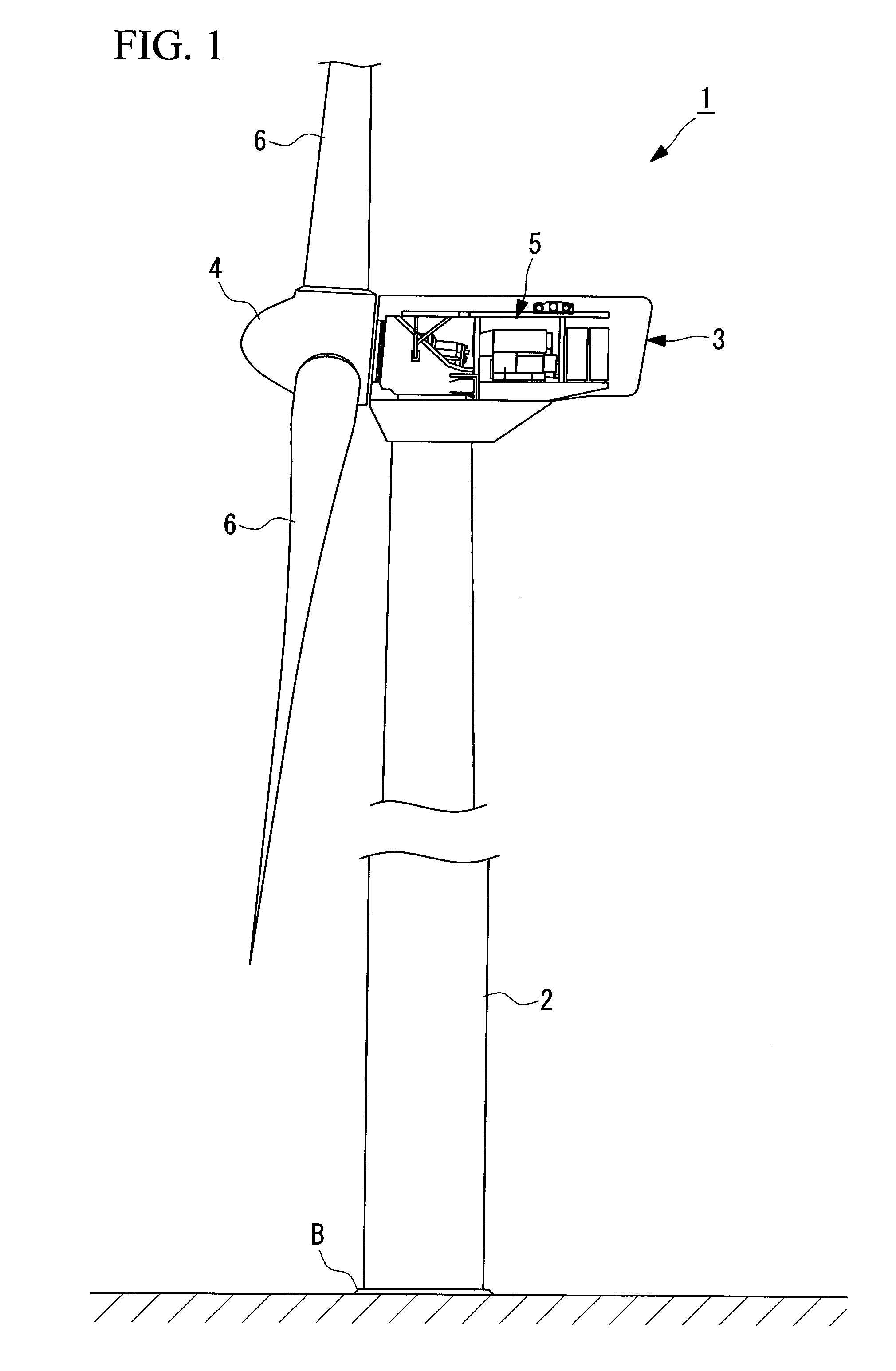
[0034]FIG. 1 is a diagram illustrating the schematic structure of the wind turbine according to this embodiment.

[0035]As shown in FIG. 1, the wind turbine 1 is for wind power generation. The wind turbine 1 includes a tower 2 vertically installed on a base B, a nacelle 3 mounted atop the tower 2, a rotor head 4 provided on the nacelle 3 so as to be rotatable around an approximately horizontal axis, and electricity-generating equipment (wind turbine equipment) 5 generating electricity through rotation of the rotor head 4.

[0036]The rotor head 4 is fitted with a plurality of wind turbine blades 6 that are arranged radially around the rotation axis thereof. With this, wind blowing against the wind turbine blades 6 from the direction of the rotation axis of the rotor head 4 generates a force on the wind turbine blades 6, causing the rotor head 4 to rotate around the...


PUM

PropertyMeasurementUnit
weightaaaaaaaaaa
weightaaaaaaaaaa
weightaaaaaaaaaa

Abstract

A method of replacing wind turbine equipment, which can reduce the cost for replacing large equipment disposed in a nacelle, is provided. The method is characterized by including a winch-hoisting step for winching up to a nacelle a reciprocating winch that is used for replacing the wind turbine equipment disposed in the nacelle mounted atop a tower and a balance supporting the wind turbine equipment with an ordinarily-installed winch provided on a girder that moves in the nacelle; a wire-hoisting step for hoisting a wire that is used for the replacement of the wind turbine equipment to the nacelle from a drum disposed on the ground; a winch-replacing step for detaching the ordinarily-installed winch from the girder and attaching the winch for replacement to the girder; and a wire-arranging step for arranging the hoisted wire on the reciprocating winch and a movable pulley provided between the balance and the girder.

Description

RELATED APPLICATIONS[0001]The present application is based on International Application Number PCT / JP2008 / 059799 filed May 28, 2008, and claims priority from Japanese Application Number 2007-161652 filed Jun. 19, 2007, the disclosures of which are hereby incorporated by reference herein in their entirety.TECHNICAL FIELD[0002]The present invention relates to a method of replacing wind turbine equipment, which is suitably used for replacing large equipment disposed in a nacelle of a wind turbine.BACKGROUND ART[0003]In general, a crane and a winch disposed in a nacelle of a wind turbine generator, which are used for maintenance, are designed so as to be used in periodic inspection and therefore have capacities capable of replacing only lightweight components in the nacelle.[0004]Therefore, when severe trouble occurred in large equipment such as a generator or a transformer, large heavy machinery has been used for replacing such large equipment. The potential risk of severe trouble occu...

Claims


Application Information

Patent Timeline
Patent Type & Authority Applications(United States)
IPC IPC(8): B23P6/00
CPCF03D1/001F03D1/003F03D11/00F05B2240/916Y10T29/49318Y02E10/722Y02E10/726Y02E10/728Y10T29/49819Y02E10/721B66C17/04B66C23/207F03D13/10F03D13/40F03D80/00F03D80/50Y02E10/72F03D80/70F05B2230/60F05B2230/80
Inventor NUMAJIRI, TOMOHIRO
Owner MITSUBISHI HEAVY IND LTD
Why Eureka
Try Eureka