

Air outlet structure of air conditioner
- Summary
- Abstract
- Description
- Claims
- Application Information
AI Technical Summary
Benefits of technology
Problems solved by technology
Method used
Image

Examples
first exemplary embodiment
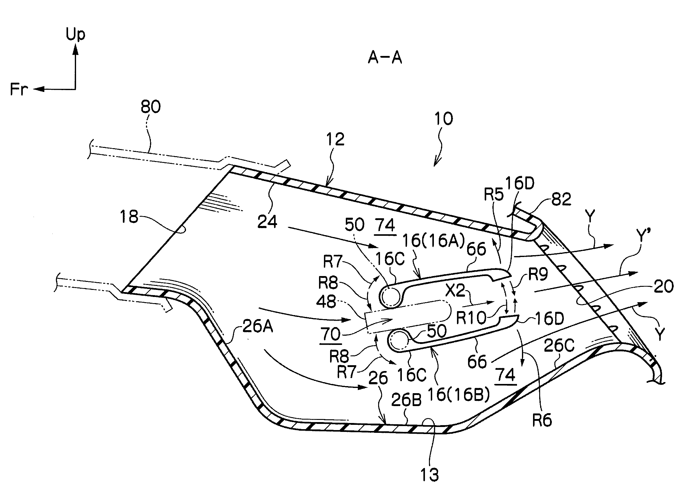
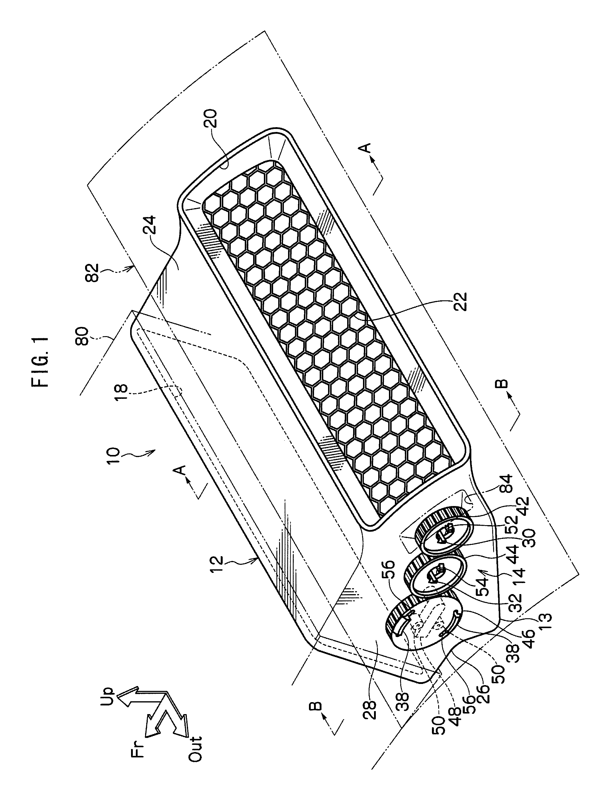
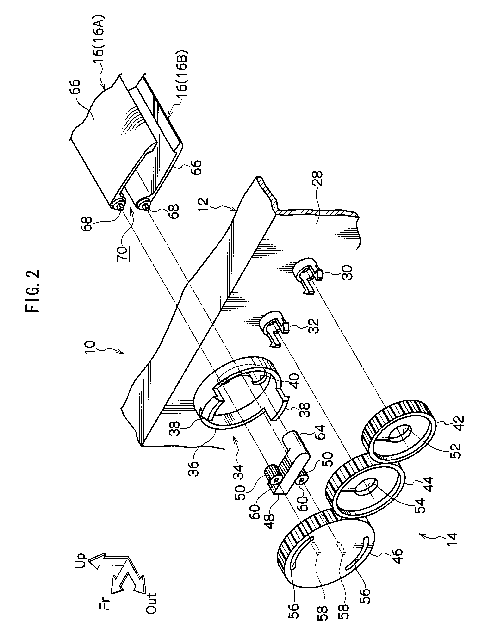
[0031]Explanation will first be given of a configuration of an air conditioner air outlet structure 10 according to a first exemplary embodiment of the present invention, with reference to FIG. 1 to FIG. 8.
[0032]FIG. 1 to FIG. 8 show the first exemplary embodiment of the present invention. FIG. 1 is a perspective view showing the overall configuration of the air conditioner air outlet structure 10. FIG. 2 is an exploded perspective view showing a configuration of an up-down delivery direction altering mechanism 14 and a pair of fins 16. FIG. 3 to FIG. 5 are cross-sections for explaining the operation of the pair of fins 16 (cross-sections taken on line A-A of FIG. 1). FIG. 6 is a cross-section on line B-B of FIG. 1. FIG. 7 and FIG. 8 are cross-sections of the air outlet structure 10 sectioned on lines C-C and D-D of FIG. 6. It should be noted that in each of the figures the arrow Fr indicates the front side in the vehicle front-rear direction, the arrow Up indicates the top side in ...
second exemplary embodiment
[0068]Explanation will now be given of the configuration of an air conditioner air outlet structure 110 according to a second exemplary embodiment of the present invention, with reference to FIG. 9 to FIG. 15.
[0069]FIG. 9 to FIG. 15 show the second exemplary embodiment of the present invention. FIG. 9 is a perspective view showing the overall configuration of the air outlet structure 110. FIG. 10 is an exploded perspective view showing a configuration of an up-down delivery direction altering mechanism 114 and a pair of fins 116. FIG. 11 to FIG. 13 are cross-sections for explaining the operation of the pair of fins 116 (cross-sections taken on line E-E of FIG. 9). FIG. 14 and FIG. 15 are explanatory diagrams of the up-down delivery direction altering mechanism 114 (cross-sections taken on line F-F of FIG. 10). It should be noted that in each of the figures the arrow Fr indicates the front side in the vehicle front-rear direction, the arrow Up indicates the top side in the vehicle up...
third exemplary embodiment
[0097]Explanation will now be given of an air conditioner air outlet structure 210 of a third exemplary embodiment of the present invention, with reference to FIG. 16 to FIG. 21.
[0098]FIG. 16 to FIG. 21 show the third exemplary embodiment. FIG. 16 is a perspective view showing the overall configuration of the air outlet structure 210. FIG. 17 is an exploded perspective view showing the configuration of an up-down delivery direction altering mechanism 214 and a pair of fins 216. FIG. 18 to FIG. 20 are cross-sectional diagrams for explaining the operation of the pair of fins 216 (cross-sections taken on line G-G of FIG. 16). FIG. 21 is a cross-sectional diagram taken on line H-H of FIG. 16. It should be noted that in each figure the arrow Fr indicates the front side in the vehicle front-rear direction, the arrow Up indicates the top side in the vehicle up-down direction, and the arrow Out indicates the outside in the vehicle width direction, respectively.
[0099]The air outlet structure...
PUM
 Abstract
Description
Claims
Application Information