
Glass forming apparatus and glass forming method

a technology of glass forming and glass forming, which is applied in the direction of glass rolling apparatus, glass making apparatus, manufacturing tools, etc., can solve the problems of not being economical, affecting the quality of glass forming, and the need to discard the forming die together with the heat exchange unit, so as to achieve favorable heat conduction, reduce cost, and enhance productivity

Inactive Publication Date: 2010-01-21
OHARA
View PDF6 Cites 0 Cited by
  • Summary
  • Abstract
  • Description
  • Claims
  • Application Information

AI Technical Summary

Benefits of technology

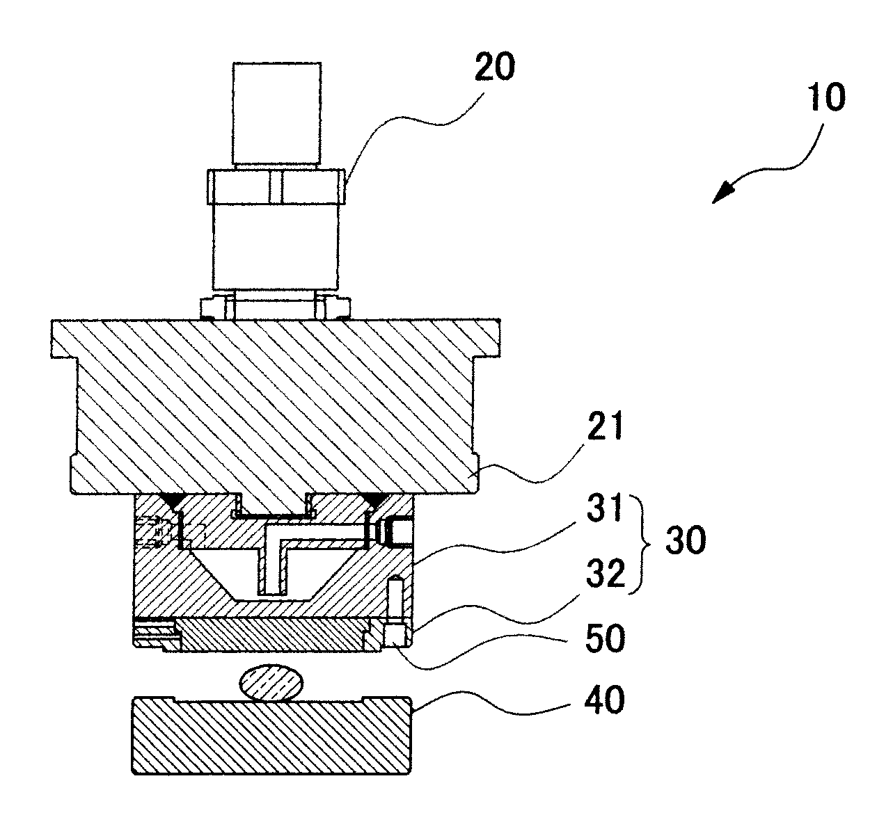
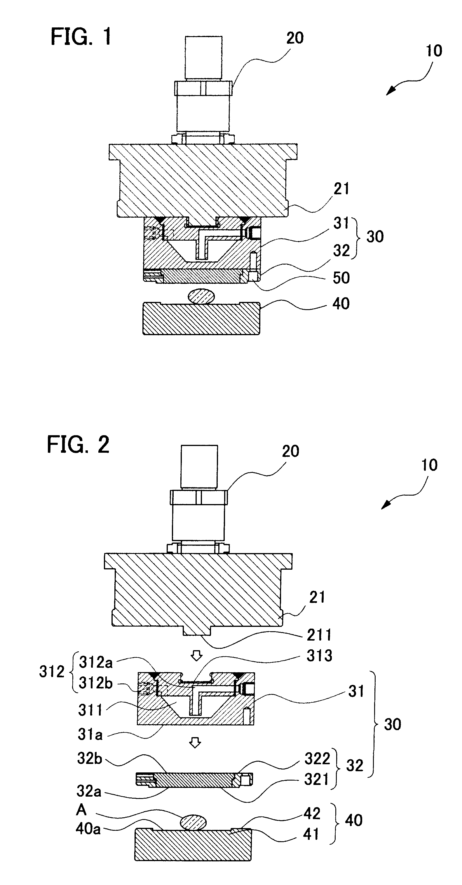
The present invention provides a glass forming apparatus and method with improved heat conduction and stable glass forming conditions. The apparatus includes a die with a press surface for pressing glass material, and at least one die is divided into a heat exchange unit and a press unit. The heat exchange unit has a heat exchange chamber and a circulating heat exchange fluid for exchanging heat with the peripheral area. The invention also provides a glass forming apparatus with a flat surface in the divided surface, a high percentage of surface precision in the divided surface, and a detachable die. The technical effects of the invention include improved production efficiency, economical production, and stable glass forming conditions.

Problems solved by technology

H10-212127, since a heat exchange unit is formed integrally in the forming die, if the wall thickness is reduced after repeated regrinding, the forming die must be discarded together with the heat exchange unit, which has not been economical.
Besides, due to cumbersome replacement operations of the forming die, the manufacturing operation is suspended for long periods, and production efficiency has been poor.

Method used


Image

  • Glass forming apparatus and glass forming method
  • Glass forming apparatus and glass forming method
  • Glass forming apparatus and glass forming method

Examples


Embodiment Construction

[0056]In the glass forming apparatus of the invention, the glass forming die is composed of a plurality of dies, and at least one of the dies is divided into a heat exchange unit and a press unit. In particular, since the press unit is in contact with the glass material and forms a glass product, is heavily worn, and is required to have a high surface precision, it must be replaced often; however, it is possible to replace only the press unit at this time, and the cost can be lowered. By quick replacement, productivity can be enhanced.

[0057]At least one part of dividing surfaces in contact with the heat exchange unit and the press unit has surface precision with flatness (PV) of 500 μm or less, more preferably 70 μm or less, or most preferably 10 μm or less, and surface roughness (Ra) of 100 μm or less, more preferably 20 μm or less, or most preferably 5 μm or less.

[0058]When the surface precision of at least one part of the dividing surfaces in contact with the heat exchange unit a...


PUM

PropertyMeasurementUnit
flatnessaaaaaaaaaa
Raaaaaaaaaaa
Raaaaaaaaaaa

Abstract

A glass forming apparatus and a glass forming method of high economical merit and high production efficiency are provided. More specifically, the glass forming apparatus has dies, in which at least one die is divided into a heat exchange unit and a press unit, and in the glass forming apparatus and glass forming method, the plane precision is improved in the contact dividing surfaces of the heat exchange unit and the press unit.A glass forming apparatus includes a die having a press surface for pressing a glass material, in which the die has a plurality of dies, and at least one die is divided into a heat exchange unit and a press unit. Preferably, the surface precision of at least one part of each dividing surface in contact with the heat exchange unit and the press unit has a flatness (PV) of 500 μm or less, and the plane precision of at least one part of the dividing surface has a surface roughness (Ra) of 100 μm or less.

Description

CROSS-REFERENCE RELATED APPLICATIONS[0001]This is a Divisional patent application of U.S. patent application Ser. No. 11 / 783,214, filed on Apr. 6, 2007, a priority from Japanese Patent Application No. 2006-107961, filed on Apr. 10, 2006, and Japanese Patent Application No. 2007-066462, filed on Mar. 15, 2007. The disclosure of the prior application is hereby incorporated by reference herein in its entirety.BACKGROUND OF THE INVENTION[0002]1. Field of the Invention[0003]The present invention relates to a glass forming apparatus and a glass forming method, and more particularly to an apparatus and a method of forming a glass substrate or a crystallized glass substrate for an information storage medium disk.[0004]2. Related Art[0005]Optical devices such as lenses and glass substrates for information storage medium disks and the like are usually manufactured by pressing and forming a glass ingot (molten glass) by either a direct press method or reheat press method.[0006]The direct press...

Claims


Application Information

Patent Timeline
Patent Type & Authority Applications(United States)
IPC IPC(8): C03B3/02C03B11/00
CPCC03B11/088C03B2215/50C03B11/12Y02P40/57
Inventor NOZAKI, MORIJI
Owner OHARA
Learn More