Multi-stroke variable displacement engine

Inactive Publication Date: 2010-01-21
FORD GLOBAL TECH LLC
View PDF3 Cites 21 Cited by
  • Summary
  • Abstract
  • Description
  • Claims
  • Application Information

AI Technical Summary

Benefits of technology

[0004]Since the power density of the engine may be increased by transitioning the engine from the four stroke cycle to the two stroke cycle, the vehicle operator's requested engine output may be met while maintaining the deactivated cylinders in the deacti

Problems solved by technology

The inventors of the present disclosure have recognized a disadvantage with the above approach.
These transitions may increase noise, vibration, and harshness (NVH) of the engine that may be perceived by the vehicle

Method used


Image

  • Multi-stroke variable displacement engine
  • Multi-stroke variable displacement engine
  • Multi-stroke variable displacement engine

Examples


Example

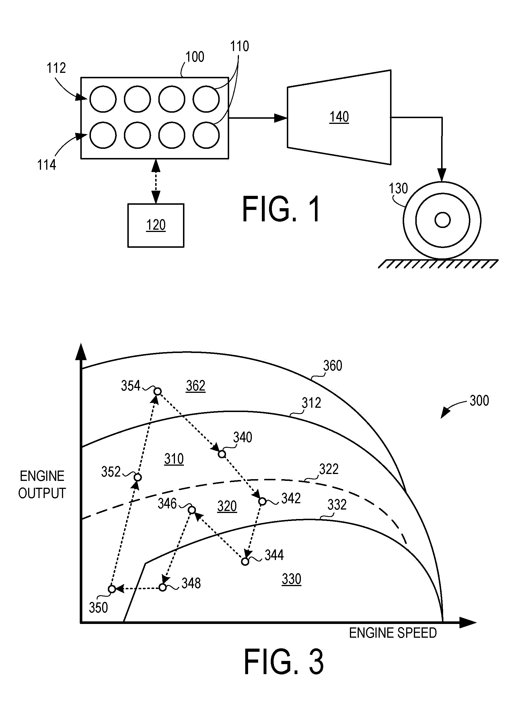
[0013]FIG. 1 illustrates a multi-stroke variable displacement internal combustion engine 100. Engine 100 may include one or more combustion chambers or cylinders 110, a non-limiting example of which is depicted schematically in FIG. 6. In some embodiments, engine 100 may be configured as a component of a vehicle propulsion system. For example, engine 100 may be operatively coupled with one or more drive wheels indicated schematically at 130 via a transmission 140. In other embodiments, engine 100 may be configured as a component of a power generation system, and may be optionally coupled with an electrical generation device such an electric machine.

[0014]Transmission 140 may include a plurality of selectable gear ratios. As will be described in the context of FIGS. 7 and 8, the transmission may be transitioned between two or more of these gear ratios responsive to the particular operating mode of the engine. For example, at least some of the engine cylinders may include multi-stroke...


PUM


Abstract

A vehicle propulsion system and method of operation are presented. As one example, the method includes operating an engine to produce an engine output; transferring the engine output to one or more drive wheels of the vehicle via a transmission; responsive to a first condition, varying torque supplied to the drive wheels by adjusting a relative number of combusting cylinders and deactivated cylinders of the engine; and responsive to a second condition, varying the torque supplied to the drive wheels by adjusting a number of strokes performed by the combusting cylinders per combustion cycle while shifting the transmission between different gear ratios.

Description

BACKGROUND AND SUMMARY [0001]Some vehicles include engines that may be partially deactivated to increase the fuel efficiency by reducing the effective displacement of the engine during select operating conditions. As such, some engines may be referred to as having a variable displacement capability, whereby combustion in one or more cylinders of the engine may be temporarily deactivated or discontinued while other cylinders of the engine continue to carry out combustion. Where increased engine output is requested by the vehicle operator, the deactivated cylinders may be activated by once again performing combustion to thereby increase the effective engine displacement and provide the requested engine output to the vehicle operator.[0002]The inventors of the present disclosure have recognized a disadvantage with the above approach. As one example, the inventors have recognized that during some conditions the above approach may result in frequent transitions from a deactivated state o...

Claims


Application Information

Patent Timeline
IPC IPC(8): F02B69/06F02D17/02
CPCF02D2400/04Y10T477/677B60W10/11F02D41/0087B60W2510/06F02B69/06B60W10/06Y10T477/679Y10T477/68F02D41/3058B60W30/188F02D2400/02Y10T477/675
Inventor SURNILLA, GOPICHANDRAMICHELINI, JOHN OTTAVIO
Owner FORD GLOBAL TECH LLC
Why Eureka
Try Eureka