Light emitting device
- Summary
- Abstract
- Description
- Claims
- Application Information
AI Technical Summary
Benefits of technology
Problems solved by technology
Method used
Image
Examples
first embodiment
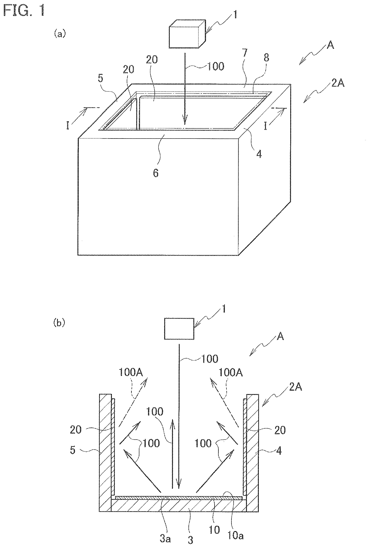
[0022]As shown in FIG. 1, a light emitting device A according to the present embodiment includes a laser light source 1 that emits a laser light, and a housing 2A including a bottom wall 3 and a side wall. The housing 2A is provided with first wavelength converters 20 containing a first phosphor. The first wavelength converters 20 are provided on the side wall.
[0023]The laser light source 1 is a light emitting element that emits a laser light 100. The laser light source 1 is not limited, but a laser diode, such as a surface emitting laser diode, may be used. An inorganic or organic electroluminescence element may be also used as the laser light source 1.
[0024]As described later, the laser light 100 emitted from, the laser light source 1 has any wavelength to be absorbed by the first phosphor contained in the first wavelength converters. Laser light has a power density higher than that of general diffused light and has high straightness and directivity.
[0025]As th...
second embodiment
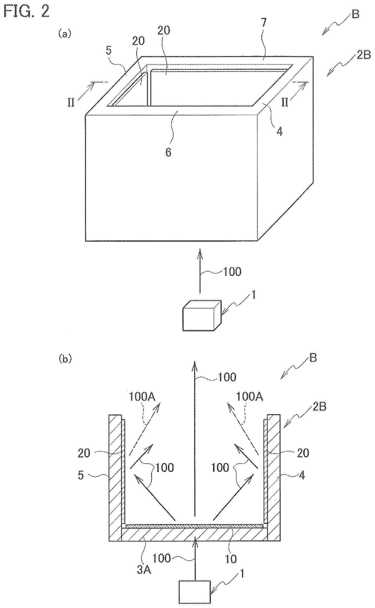
[0088]Next, a light emitting device according to a second embodiment is described in detail with reference to the drawings. Note that the same components as those of the light emitting device according to the first embodiment are denoted by the same reference numerals, and redundant descriptions are omitted.
[0089]As shown in FIG. 2, a light emitting device B according to the present embodiment includes a laser light source 1 that emits laser light, and a housing 2B that includes a bottom wall 3A and a side wall. The housing 2B includes first wavelength converters 20 provided on the side wall. The first wavelength converters 20 contain a first phosphor. The housing 2B includes the bottom wall 3A, and the side wall including a right wall 4, a left wall 5, a front wall 6, and a rear wall 7. The housing 2B has a substantially rectangular parallelepiped shape when viewed from the outside. The housing 2B has an internal space partitioned by the bottom wall 3A, the right wall 4, the left w...
third embodiment
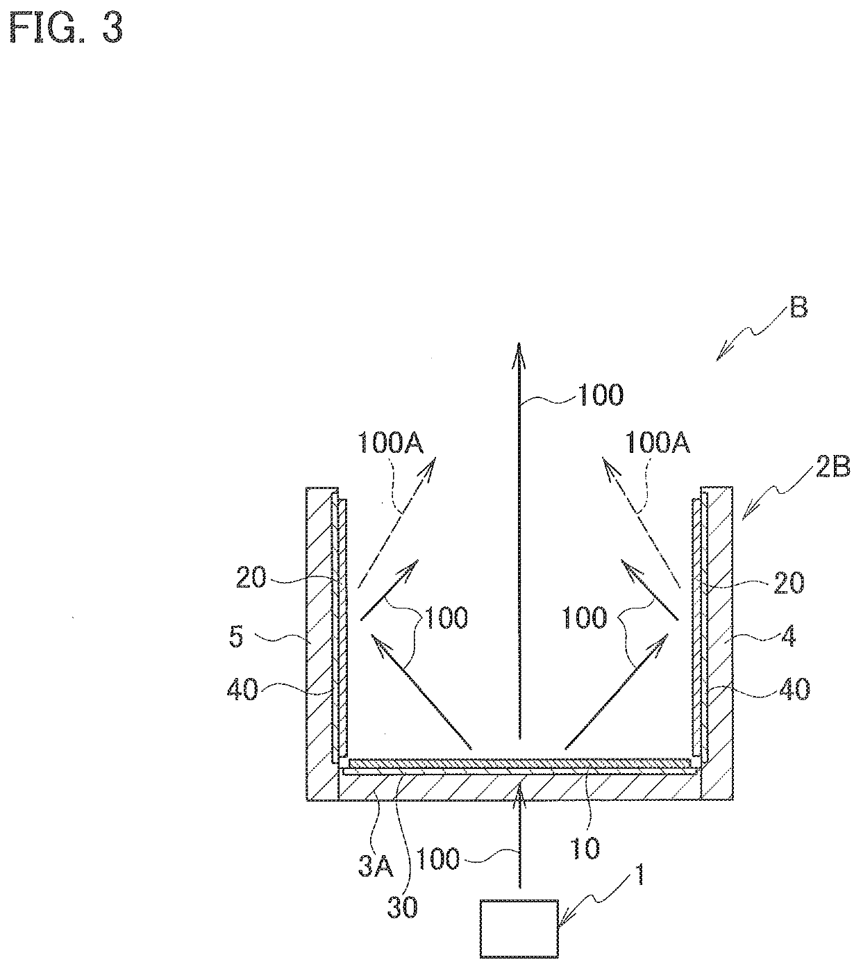
[0099]Next, a light emitting device according to a third embodiment is described in detail with reference to the drawings. Note that the same components as those of the light emitting devices according to the first and the second embodiments are denoted by the same reference numerals, and redundant descriptions are omitted.
[0100]As described above, the light emitting devices A and B according to the first and second embodiments include the housings 2A and 2B that include the bottom walls 3 and3A, and the side wall including the right wall 4, the left wall 5, the front wall 6, and the rear wall 7 and have a substantially rectangular parallelepiped shape when viewed from the outside. However, the shape of the housing used in the light emitting device according to the present embodiment is not limited to such a substantially rectangular parallelepiped shape, and shapes shown in FIGS. 4 to 7 may be used, The laser light source 1 is omitted in FIGS. 4 to 7.
[0101]FIG. 4 shows a modificati...
PUM
 Abstract
Description
Claims
Application Information
 - R&D
- Intellectual Property
- Life Sciences
- Materials
- Tech Scout
- Unparalleled Data Quality
- Higher Quality Content
- 60% Fewer Hallucinations
Browse by: Latest US Patents, China's latest patents, Technical Efficacy Thesaurus, Application Domain, Technology Topic, Popular Technical Reports.
© 2025 PatSnap. All rights reserved.Legal|Privacy policy|Modern Slavery Act Transparency Statement|Sitemap|About US| Contact US: help@patsnap.com


