Light emitting device

a light emitting device and light source technology, applied in semiconductor devices, light sources, lighting and heating apparatus, etc., can solve the problems of chromaticity flexibility and the inability to extract light from the emitting part, and achieve the effect of improving color uniformity and chromaticity flexibility, and increasing the power density of output ligh

Active Publication Date: 2022-06-28
PANASONIC INTELLECTUAL PROPERTY MANAGEMENT CO LTD
View PDF19 Cites 0 Cited by
  • Summary
  • Abstract
  • Description
  • Claims
  • Application Information

AI Technical Summary

Benefits of technology

[0007]The present invention has been made in consideration of such problems as described above, which are inherent in the prior art. An object of the present invention is to provide a light emitting device that improves color uniformity and chromaticity flexibility while increasing power density of output light.

Problems solved by technology

However, in the light emitting device in Patent Literature 1, the extraction efficiency of the light from the emitting part sometimes decreases as the light scattering inside the phosphor becomes excessive.
Accordingly, when the excitation light is a blue light having a wavelength of 440 to 490 nm, for example, it is difficult for the light emitting device to obtain a color tone in a low color temperature range, resulting in little flexibility in chromaticity.

Method used


Image

  • Light emitting device
  • Light emitting device
  • Light emitting device

Examples


first embodiment

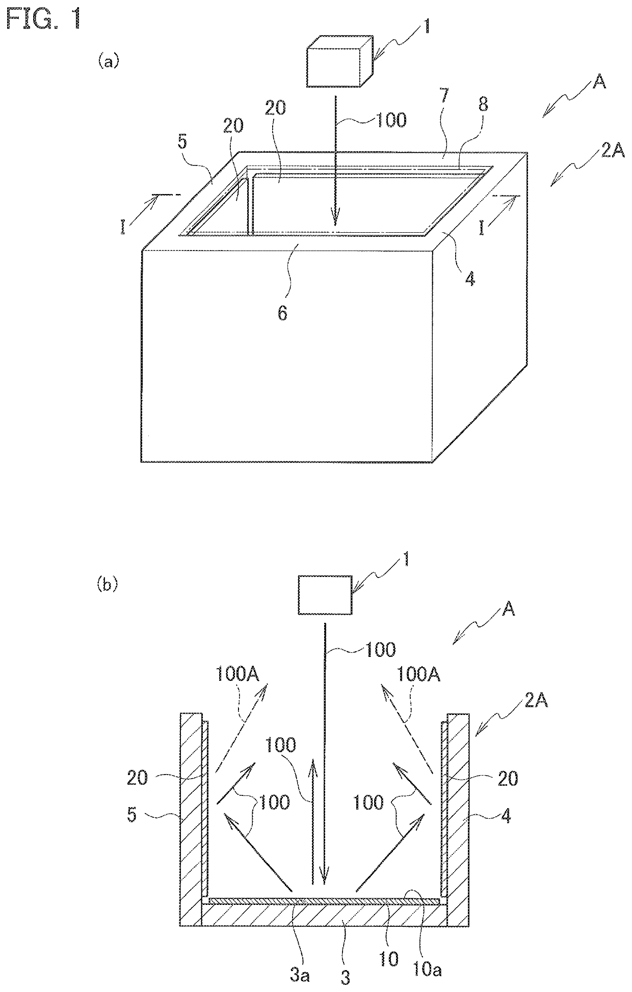
[0022]As shown in FIG. 1, a light emitting device A according to the present embodiment includes a laser light source 1 that emits a laser light, and a housing 2A including a bottom wall 3 and a side wall. The housing 2A is provided with first wavelength converters 20 containing a first phosphor. The first wavelength converters 20 are provided on the side wall.

[0023](Laser Light Source)

[0024]The laser light source 1 is a light emitting element that emits a laser light 100. The laser light source 1 is not limited, but a laser diode, such as a surface emitting laser diode, may be used. An inorganic or organic electroluminescence element may be also used as the laser light source 1.

[0025]As described later, the laser light 100 emitted from, the laser light source 1 has any wavelength to be absorbed by the first phosphor contained in the first wavelength converters. Laser light has a power density higher than that of general diffused light and has high straightness and directivity.

[0026...

second embodiment

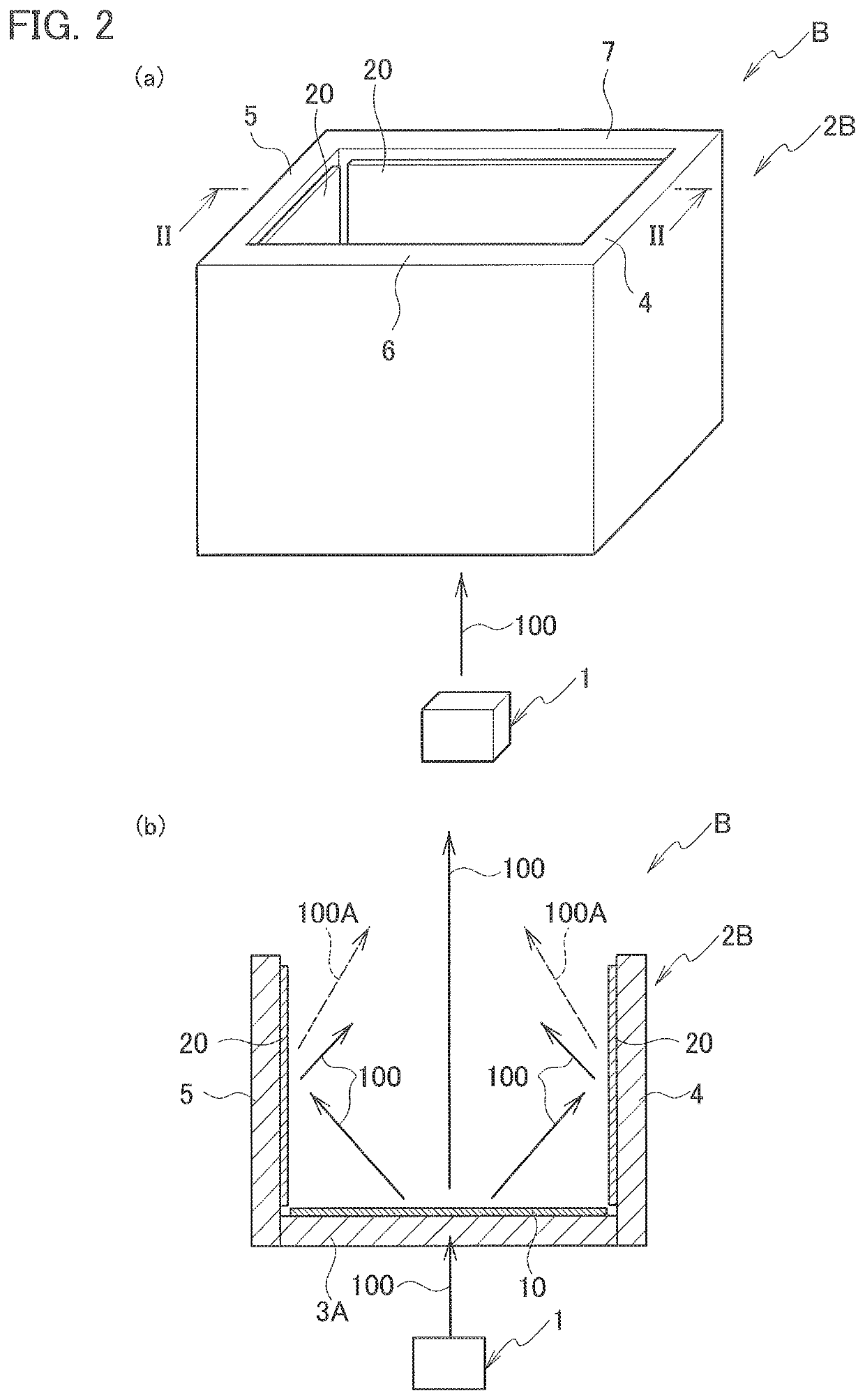
[0092]Next, a light emitting device according to a second embodiment is described in detail with reference to the drawings. Note that the same components as those of the light emitting device according to the first embodiment are denoted by the same reference numerals, and redundant descriptions are omitted.

[0093]As shown in FIG. 2, a light emitting device B according to the present embodiment includes a laser light source 1 that emits laser light, and a housing 2B that includes a bottom wall 3A and a side wall. The housing 2B includes first wavelength converters 20 provided on the side wall. The first wavelength converters 20 contain a first phosphor. The housing 2B includes the bottom wall 3A, and the side wall including a right wall 4, a left wall 5, a front wall 6, and a rear wall 7. The housing 2B has a substantially rectangular parallelepiped shape when viewed from the outside. The housing 2B has an internal space partitioned by the bottom wall 3A, the right wall 4, the left w...

third embodiment

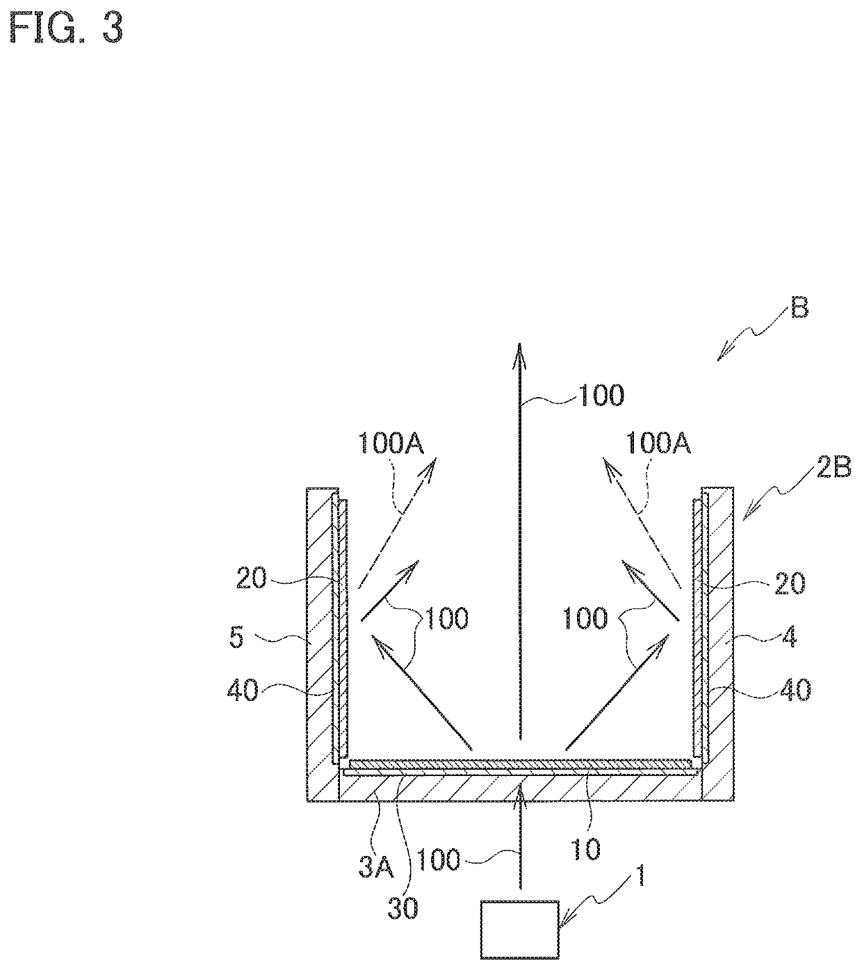
[0103]Next, a light emitting device according to a third embodiment is described in detail with reference to the drawings. Note that the same components as those of the light emitting devices according to the first and the second embodiments are denoted by the same reference numerals, and redundant descriptions are omitted.

[0104]As described above, the light emitting devices A and B according to the first and second embodiments include the housings 2A and 2B that include the bottom walls 3 and 3A, and the side wall including the right wall 4, the left wall 5, the front wall 6, and the rear wall 7 and have a substantially rectangular parallelepiped shape when viewed from the outside. However, the shape of the housing used in the light emitting device according to the present embodiment is not limited to such a substantially rectangular parallelepiped shape, and shapes shown in FIGS. 4 to 7 may be used. The laser light source 1 is omitted in FIGS. 4 to 7.

[0105]FIG. 4 shows a modificat...


PUM

PropertyMeasurementUnit
wavelength rangeaaaaaaaaaa

Abstract

Alight emitting device (A) includes a laser light source (1) that emits laser light (100), a housing (2A) that includes a bottom wall (3) and a side wall, and a first wavelength converter (20) provided on the side wall, the first wavelength converter (20) containing a first phosphor. The bottom wall of the housing is irradiated with the laser light emitted from the laser light source, and the first phosphor is excited by diffused light of the laser light diffused by the bottom wall. With such a configuration, the light emitting device (A) improves color uniformity and chromaticity flexibility while increasing power density of output light.

Description

TECHNICAL FIELD[0001]The present invention relates to a light emitting device.BACKGROUND ART[0002]A light emitting device that utilizes photoluminescence of a phosphor using laser light as excitation light and obtains white light from mixture of a part of the laser light and fluorescence emitted from the phosphor has been known.[0003]To improve light output of the light emitting device, it is awaited to irradiate the phosphor with excitation light having a high power density. It is however known that the saturation of fluorescent output of the phosphor occurs with the increase in the power of the excitation light, and thus the conversion efficiency from laser light to white light may decrease. Moreover, fluorescence has orientation distribution with isotropic diffusion (non-directivity), while laser light has high straightness (directivity). Due to such properties of fluorescence and laser light, color irregularity may occur in the irradiation spot of the output light, and color uni...

Claims


Application Information

Patent Timeline
Patent Type & Authority Patents(United States)
IPC IPC(8): F21V7/26F21V15/01H01S5/022H01S5/0239
CPCF21V7/26F21V15/01H01S5/022F21V7/05F21Y2115/30F21K9/62F21V9/20F21V9/30H01S5/02251H01S5/0087H01S5/32341F21K9/64H01S5/0239
Inventor OKUNO, TATSUYAABE, TAKESHIOSHIO, SHOZO
Owner PANASONIC INTELLECTUAL PROPERTY MANAGEMENT CO LTD
Why Eureka
Try Eureka