Power module

Inactive Publication Date: 2015-03-26
DELTA ELECTRONICS SHANGHAI CO LTD
View PDF6 Cites 7 Cited by
  • Summary
  • Abstract
  • Description
  • Claims
  • Application Information

AI Technical Summary

Benefits of technology

[0009]In summary, a driving electrode of the power device is electrically coupled to the first metal layer or a driving component on the first metal layer. The gap within the first metal layer is formed by isotropic etching, and since the thickness of the first metal layer is merely between 5 μm and 50 μm, a width of the lateral etching is not

Problems solved by technology

However the high-temperature sintering process requires high energy consumption and therefore does not meet the trend of energy-saving.
However, as the copper layer gets thicker, the copper layer needs to be eroded deeper for etching.
However, such thickness is diffic

Method used


Image

  • Power module
  • Power module
  • Power module

Examples


Example

First Embodiment

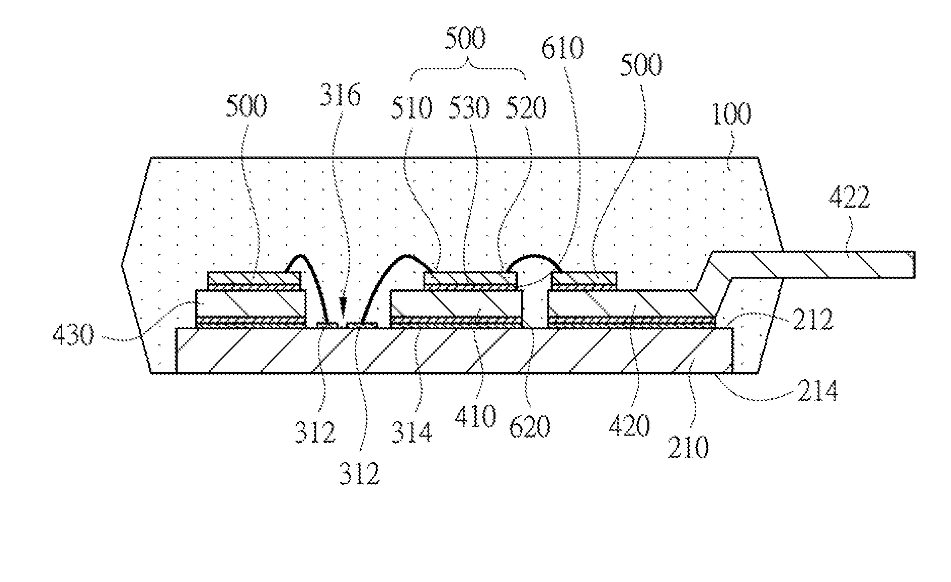
[0032]FIG. 1 is a diagram illustrating a cross-sectional view of a power module according to a first embodiment of the present invention. As shown in FIG. 1, the power module comprises a sealing body 100 and a first substrate 210. A first metal layer 210, a second metal layer 314, conductive structures 410, 420 and 430, and at least one power device 500 are disposed on the first substrate 210. The first substrate 210 is disposed in the sealing body 100. The sealing body 100 covers at least the first metal layer 312, the conductive structures 410 and 430, a part of the conductive structure 420 and the power device 500 for protection. The conductive structure 420 has an exposed part 422. The exposed part 422 is exposed out of the sealing body 100, and electrically connects to an external device. The exposed part 422 can be realized by a lead frame, for instance. The first substrate 210 comprises a top side 212 and a bottom side 214 which are relative to each other. The...

Example

Second Embodiment

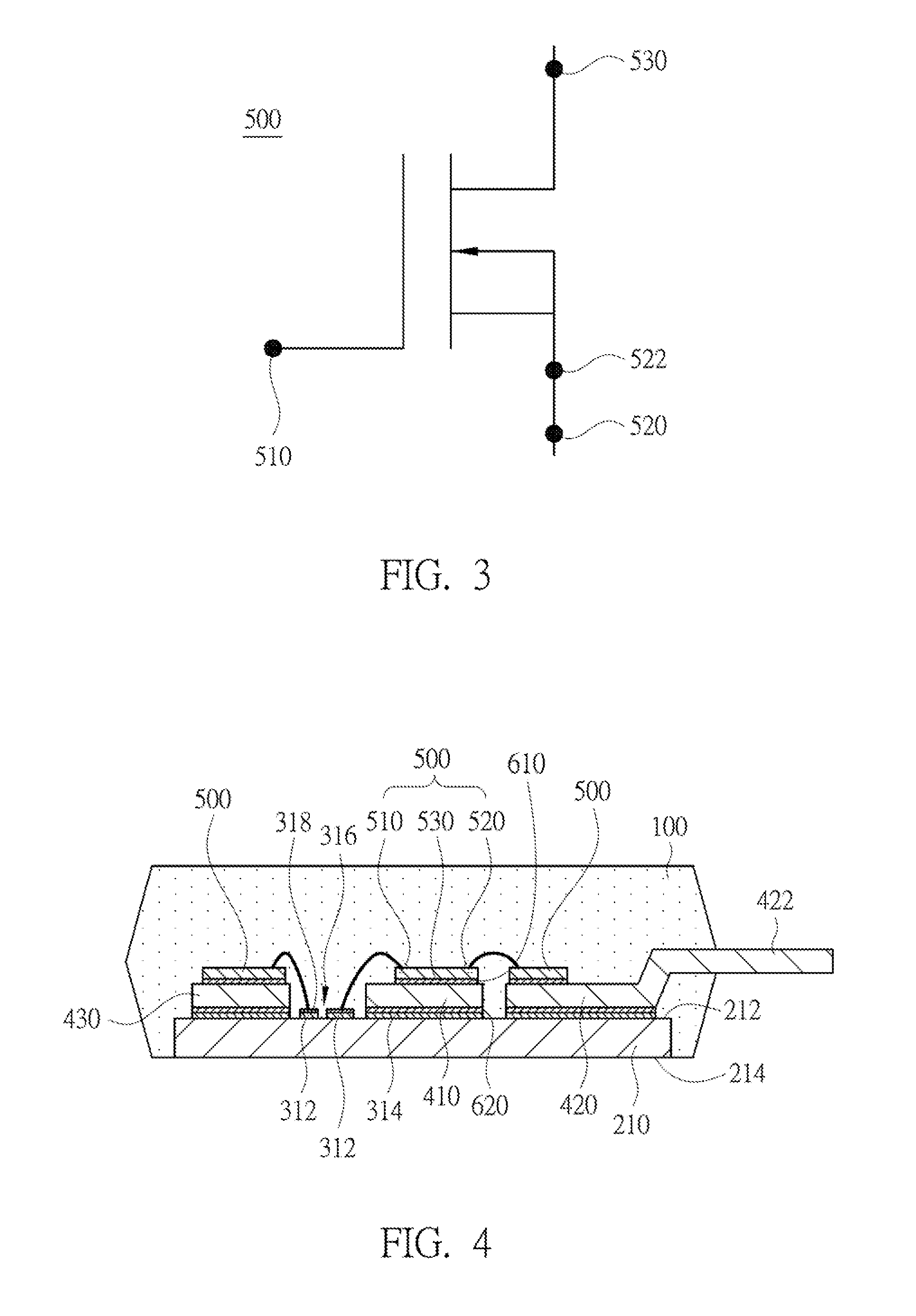
[0040]FIG. 4 is a diagram illustrating a cross-sectional view of a power module according to a second embodiment of the present invention. The present embodiment differs to the first embodiment mainly in that the power module of the present embodiment further comprises a plurality of flattening structures 318. The flattening structure 318 is disposed on a surface, which is opposite to the first substrate 210, of the first metal layer 312. The flattening structure 318 has a flat upper surface, which is suitable for wirings. For instance, the flattening structure 318 can be realized by a coating of platted nickel, silver, nickel gold or platted palladium, etc., on the first metal layer 312. Other technical features of the present embodiment are similar to those of the first embodiment, so relative descriptions are omitted hereinafter.

Example

Third Embodiment

[0041]FIG. 5 is diagram illustrating a cross-sectional view of a power module according to a third embodiment of the present invention. The present embodiment differs to the first embodiment mainly in that the power module of the present embodiment further comprises an adhesive structure 710. The adhesive structure 710 is disposed between the conductive structure 410 and the first substrate 210, so as to conduct the heat of the conductive structure 410 to the first substrate 210. By also referring to FIG. 1 and FIG. 3 together, it can be observed that the adhesive structure 710 has replaced the second metal layer 314 and the bonding layer 620 under the conductive structure 410. Since the second metal layer 314 is omitted in the present embodiment, the manufacturing cost of the second metal layer 314 can be further saved. In the present embodiment, the adhesive structure 710 can be disposed below the conductive structure 410 so as to fill the gap between the conductiv...


PUM


Abstract

A power module is disclosed. The power module includes a first substrate, a first metal layer, at least one conductive structure and at least one power device. The first metal layer is disposed on the first substrate. The first metal layer has a first thickness d1. The first thickness d1 satisfies: 5 μm≦d1≦50 μm. The conductive structure is disposed at a position different to the first metal layer on the first substrate. The conductive structure has a second thickness d2. The second thickness d2 satisfies: d2≧100 μm. The power device is disposed on the first substrate, the first metal layer or the conductive structure. The driving electrode of the power device is electrically connected to the first metal layer. The power electrode of the power device is electrically coupled to the conductive structure.

Description

RELATED APPLICATIONS[0001]This application claims priority to China Application Serial Number 201310435466.X, filed Sep. 23, 2013, which is herein incorporated by reference.BACKGROUND[0002]1. Technical Field[0003]Embodiments of the present invention relate to a power module. More particularly, embodiments of the present invention relate to a power module for a power converter.[0004]2. Description of Related Art[0005]A semiconductor power device is an indispensable part in a conventional power converter. Power density of a power device corresponds to an output power of the power module per unit volume. For the same output power, the higher the power density, the smaller the power module, so less space is occupied. Therefore, having a high power density has always been an industrial requirement for power modules. To increase the power density of a power device, an integrated power module (IPM) is developed. The IPM integrates a number of semiconductor devices into a package, so high o...

Claims


Application Information

Patent Timeline
IPC IPC(8): H05K1/02H05K1/11H05K1/18
CPCH05K1/0298H05K2201/09H05K1/11H05K1/181H01L2224/48091H01L2224/48137H01L2224/73265H01L2924/13055H05K1/0265H05K2201/10166H01L23/36H01L23/49811H01L23/49833H01L23/4334H01L23/49537H01L23/49562H01L23/49575H01L23/49568H01L25/072H01L2924/181H01L2924/13091H01L23/3735H01L2924/00014H01L2924/00H01L2924/00012
Inventor HONG, SHOU-YUZHOU, GAN-YUZENG, JIAN-HONGZHAO, ZHEN-QING
Owner DELTA ELECTRONICS SHANGHAI CO LTD
Why Eureka
Try Eureka