
Large-ratio strain wave gearing speed changing apparatus

Inactive Publication Date: 2014-11-27
LIN PANCHIEN
View PDF4 Cites 7 Cited by
  • Summary
  • Abstract
  • Description
  • Claims
  • Application Information

AI Technical Summary

Benefits of technology

The present invention relates to a speed changing apparatus that uses strain wave gearing. The technical effects of the invention include increased power density, improved efficiency, and reduced flexing in components, leading to improved service life.

Problems solved by technology

However, this cascaded speed reduction suffers in overall speed-changing efficiency due to its nature of having the entire load passing successively through each and every reducer stage of the cascade.
The arrangement is also bulky for the obvious reason that each stage in the cascade must be fully rated to handle one hundred percent of the total power delivered by the prime mover.
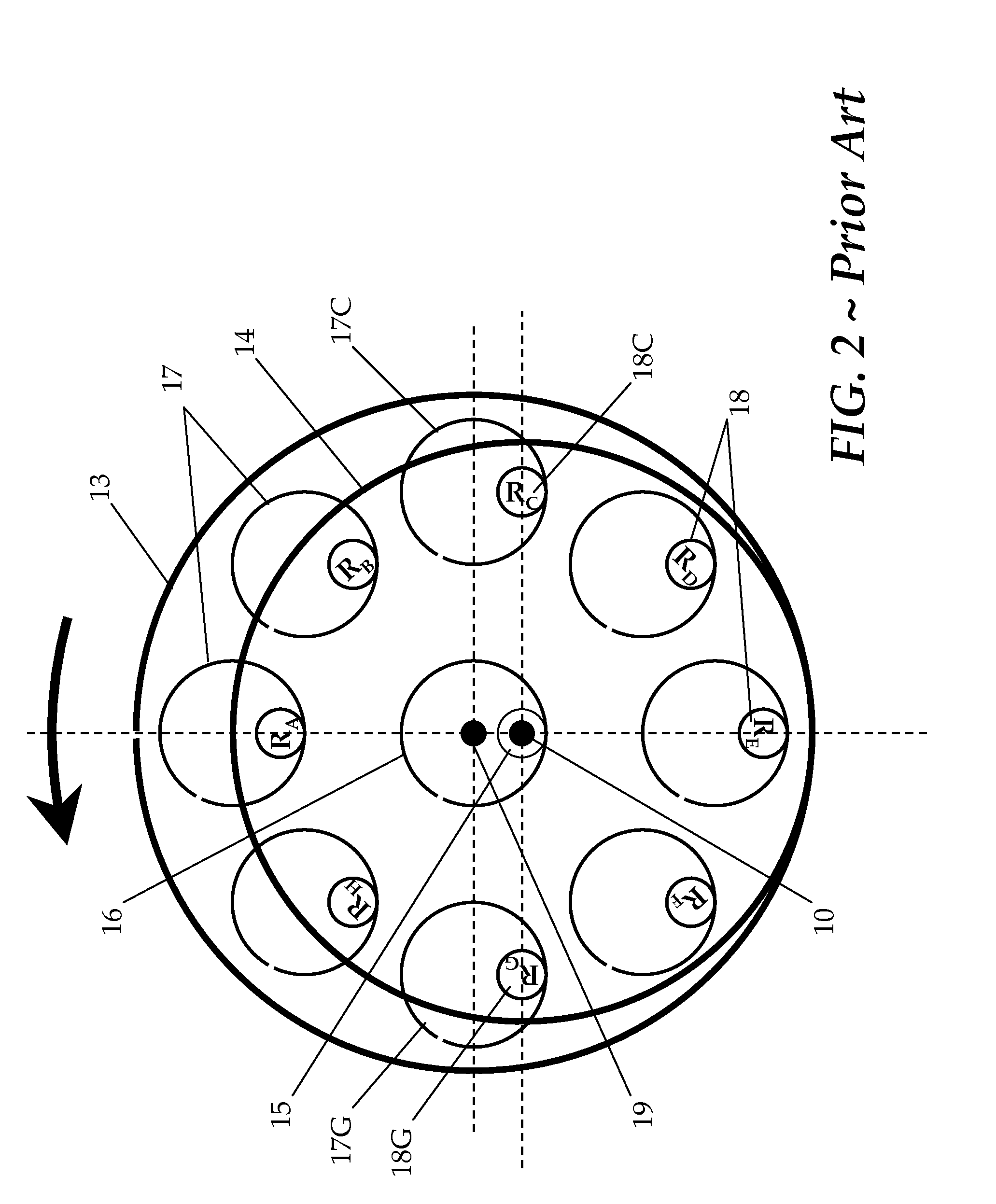
But this is not an optimized mechanism due to low utilization: Of all eight pin / hole pairs shown in FIG. 2, half (four or even five depending on the angular position) of them are not in the position to drive the load.
With limitations such as these, cycloidal drives achieve typically less than 80 percent efficiency under normal load conditions.
For large ratio, the large ring gear number makes the drive bulky if the rated torque is substantial therefore the teeth must be sufficiently robust—in size.
In other words, compactness of the cycloidal drive places a limitation on the torque and power rating of the drive.
Operating the basic concept known as strain wave gearing, harmonic drive is relatively low in available power rating.
The drive also delivers typically less than 60 percent efficiency under normal load because its spline element flexes all the time as the drive operates to transmit mechanical power.
Although physically different in construction compared to cycloidal drives, conventional strain wave gearing speed changing devices suffer the same drawbacks in terms of characteristics such as power rating and power-to-weight ratio described above.

Method used


Image

  • Large-ratio strain wave gearing speed changing apparatus
  • Large-ratio strain wave gearing speed changing apparatus
  • Large-ratio strain wave gearing speed changing apparatus

Examples


Embodiment Construction

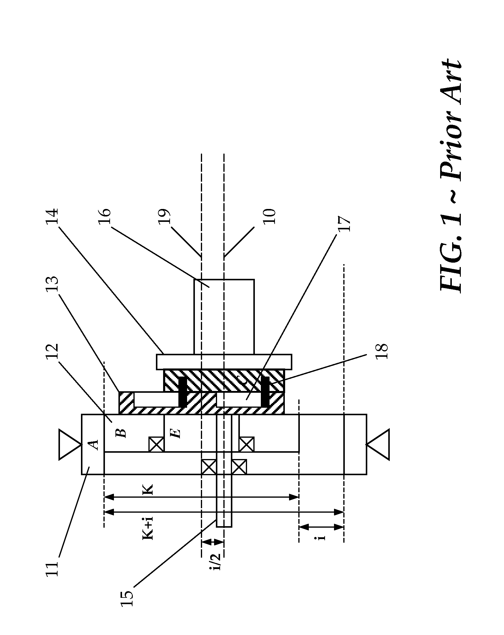
[0041]FIG. 3 is a cross-sectional configuration of a speed changing apparatus of the present invention that schematically illustrates an equivalent arrangement of the off-axis power extraction stage thereof. With simultaneous reference also to FIGS. 1 and 2, instead of the plate 14 with multiple pin-rollers 18 that engages with their corresponding holes 17 formed in the cycloidal disc 13, a speed changing apparatus of the present invention has a different arrangement for power extraction.

[0042]As is illustrated, while the planet gear 32 moves epicyclically inside the frame ring gear 31 as a first ring-spur gear pair, another planet gear 33 that is fixed coaxially with gear 32 also moves epicyclically inside its ring gear 34, a second pair of ring-spur gears. As the gear 33 spins and moves epicyclically inside gear 34, its outer most edge (of its pitch circle) 33P plots a trace 33T. This trace 33T is made to exactly coincide with the pitch circle of the ring gear 34. Essentially, rin...


PUM


Abstract

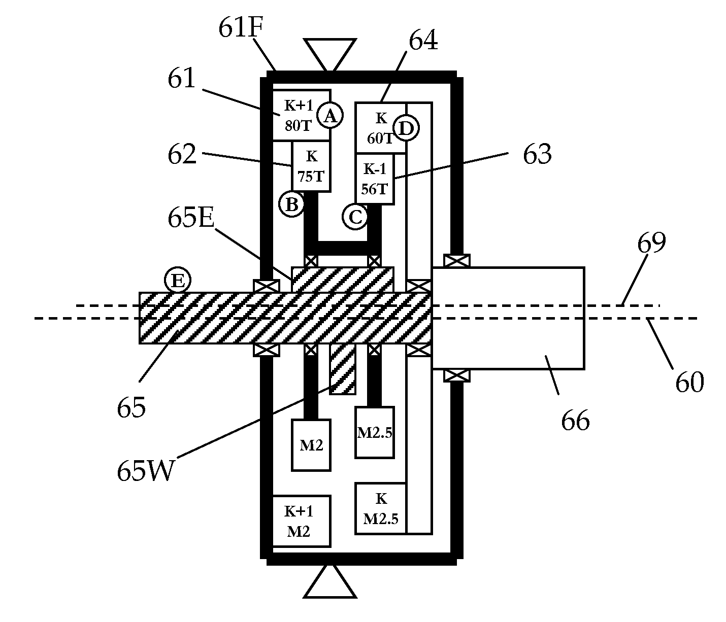
A strain wave gearing speed changing apparatus for changing an input speed to an output either greatly slower or faster, the apparatus has a coaxial pair of circular splines that includes a first circular spline having a tooth number TA and a second circular spline having a tooth number TD. A coaxial pair of flex splines includes a first flex spline having a tooth number TB and a second flex spline having a tooth number TC. The first flex spline meshes with the first circular spline and the second flex spline meshes with the second circular spline at two, preferably more meshing engagements. A wave generator is connected to one of the input and output shafts of the apparatus. Two splines of one of the two coaxial pairs being fixed together to operate flexingly on the wave generator that may have equal spline tooth engagement pitch circle circumference lengths. One spline of the other of the two coaxial pairs being fixed to the frame of the apparatus and the other spline being connected to the other of the input and output shafts. In the apparatus, the four splines satisfy the dimensional relationship of TA=TK+Ti, TB=TK, TC=TK−Tj and TD=TK+Ti−Tj.

Description

CROSS-REFERENCE TO RELATED APPLICATIONS[0001]This application is a Continuation-in-Part of U.S. patent application Ser. No. 13 / 289,477 filed Nov. 4, 2011, which claims benefit of U.S. Provisional Application Ser. No. 61 / 410,245 filed Nov. 4, 2010, the disclosure which is hereby incorporated by reference in its entirety.BACKGROUND[0002]1. Field of the Invention[0003]The present invention relates in general to speed changing apparatus and, in particular, to large-ratio speed changing apparatus. More particularly, the present invention relates to a large-ratio strain wave gearing speed changing apparatus for both speed reduction and speed increase applications with improved power capacity and service life.[0004]2. Description of the Related Art[0005]Speed changing is indispensable. Frequently a prime mover must work at high rotational speeds for optimized efficiency while the load it drives must run at tenths or even hundredths its speed. One way to obtain such large speed reduction ra...

Claims


Application Information

Patent Timeline
IPC IPC(8): F16H49/00
CPCF16H2049/003F16H49/001Y10T74/19642
Inventor LIN, PANCHIEN
Owner LIN PANCHIEN
Learn More