Optical printers

a technology of optical printers and optical plates, applied in printers, pile separation, printing, etc., can solve the problems of affecting the quality of images, limiting the resolution achievable, and affecting the physical size of the illumination device, so as to reduce the possibility of the medium slipping

Inactive Publication Date: 2010-01-21
LUMEJET HLDG
View PDF4 Cites 3 Cited by
  • Summary
  • Abstract
  • Description
  • Claims
  • Application Information

AI Technical Summary

Benefits of technology

[0039]By arranging the light source arrays along notional parallel lines on the substrate, and offsetting the individual elements of each array with respect to the associated notional line—in effect by providing arrays of castellated light emitting elements—it is possible to more closely arrange the light emitting elements in a dimension parallel to the aforementioned notional lines than it is in the prior art arrangement depicted in FIG. 2(a). By more closely arranging the elements in this way the spacing of individual components of the final image that are attributable to respective elements can be reduced, thereby improving the resolution of that image.
[0045]This aspect of the present invention is advantageous because the first surface of the substrate reduces cross-talk between adjacent arrays, and the mask reduces cross-talk between adjacent elements of an array and between elements of adjacent arrays. By this we mean that, for a given element, a greater component of the light coming from that part of the array (which light illuminates a group of fibres in the taper) is actually attributable to that element (as opposed to being light reflected from adjacent elements or arrays).
[0047]A fifth aspect of the present invention provides a transport mechanism for an optical printer, the mechanism comprising: a transport roller for transporting photographic medium, at least one region of the exterior surface of the transport roller being configured to grip and drag photographic medium through the transport mechanism and towards a printing head assembly; a pressure roller configured to press photographic medium against the transport roller to thereby reduce the possibility of the medium slipping as it is advanced by the transport roller; guide means for guiding photographic medium from at least one storage canister to the pressure roller and transport roller; a stepper motor configured to rotate the transport roller; means for detecting rotation of the transport roller and generating a signal that is representative thereof; and a controller that is configured to control the stepper motor to drive the transport roller to advance medium a predetermined distance through the transport mechanism, to derive from said signal a measure of the distance rotated by the roller, and to control the stepper motor to cease rotation of the roller when the measured distance is equal to said predetermined distance.

Problems solved by technology

In an optical printer a key limiting factor for the achievable resolution is the size of the illumination device used to generate the light that impinges on the photographic medium.
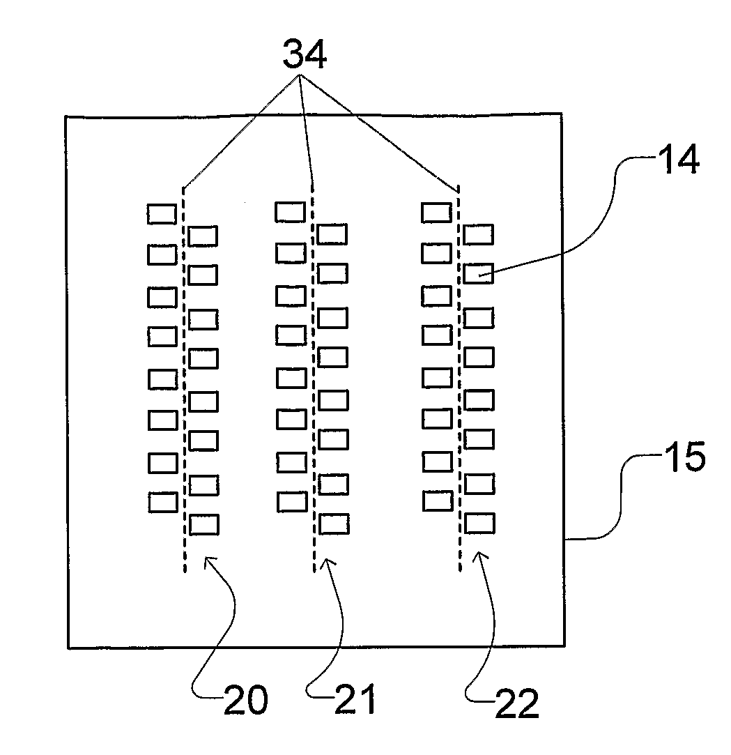
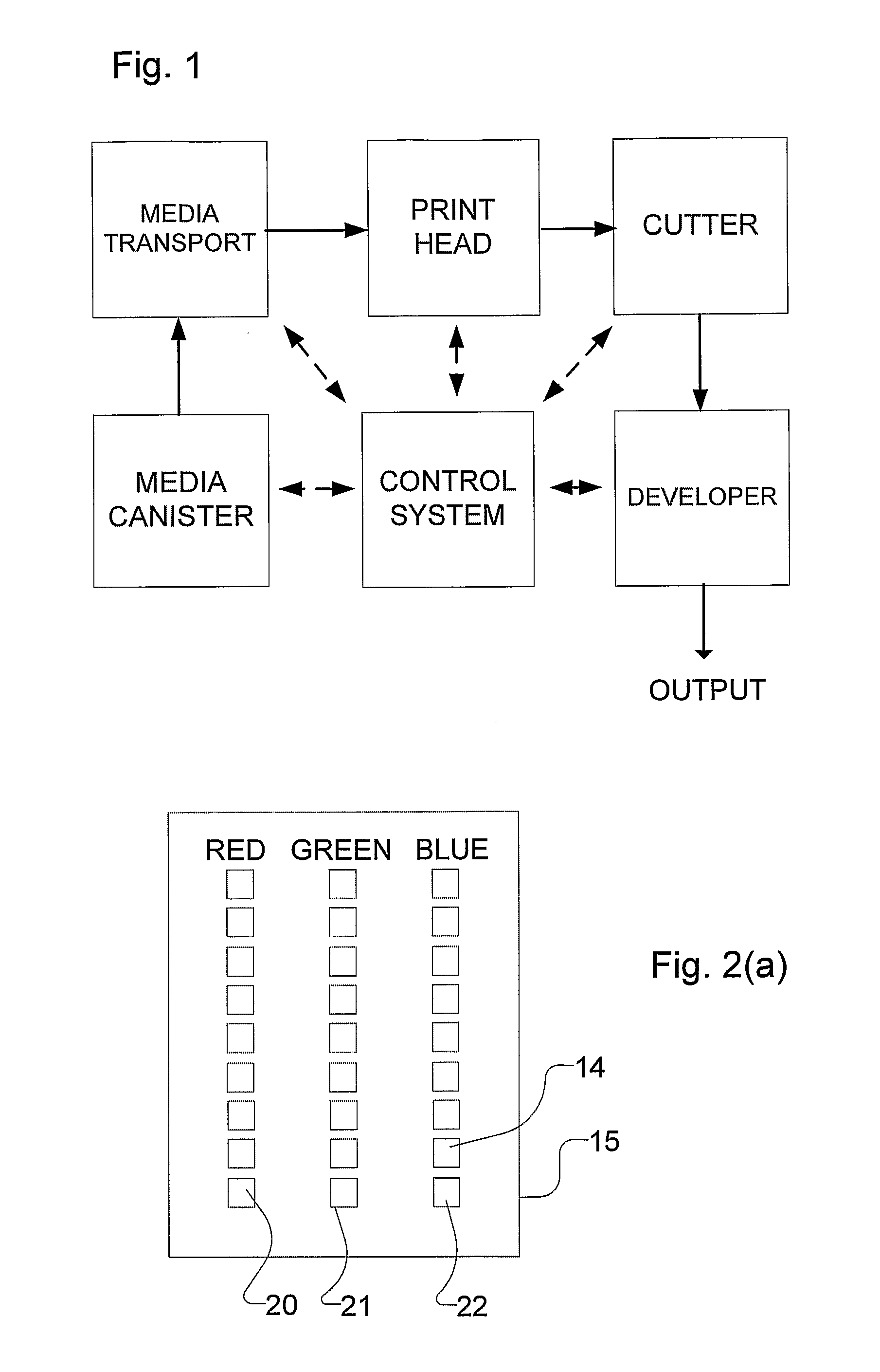
However, we have found that our attempts to reduce the physical size of the illumination device have been hampered inter alia by the physical size of the—typically LED—light emitting elements of the red, green and blue arrays that make up the illumination device, and the spacing between the elements that must be provided to enable the elements to be connected to an electrical power source.
With previously proposed devices, such as that disclosed in our prior patent, we have noticed that the quality of the image can sometimes be adversely affected by a so-called “banding” effect that can occur at the junction between successive printing swathes as the image is being formed on the photographic medium.
Whilst this arrangement works well, apparently insignificant errors in the amount paper advanced between the printing of successive swathes, and other operational irregularities, can detrimentally affect the final image.
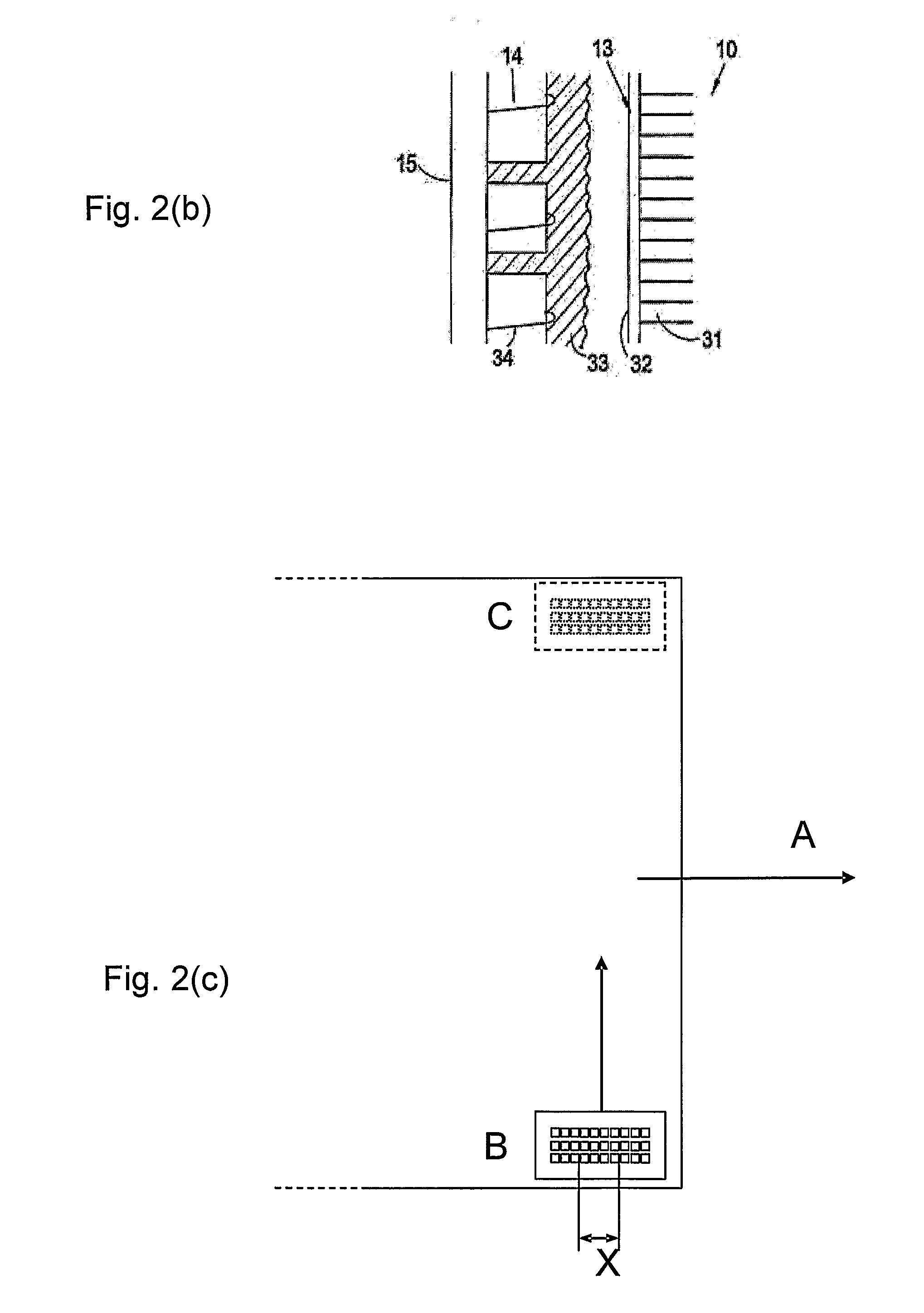
For example, advancing the paper by a length greater than X can cause a detectable gap (visible as a white line) between successive swathes, whereas advancing the paper by a length less than X can result in an overexposure of the photographic medium (visible as a noticeably darker band) in the region where the swathes overlap.
Whilst this previously proposed illumination device has functioned adequately, we have noted that the quality of the final image can sometimes be adversely affected by crosstalk between adjacent LED elements, and by variations in the relative intensities of the red, green and blue arrays.
It is also the case that maintenance of the gap between the illumination device and fibre optic light pipe must be carefully controlled (to avoid aberrations in the final image) and such control can be difficult to achieve in practice.
A persistent problem for optical printers, particularly those printers that use LEDs for light sources, is that the characteristics of the light sources vary dramatically from one to the other.
It is also the case that light emitting diodes tend to vary non-linearly in both their output intensity and wavelength with input voltage variations, and a compounding problem is that the photographic medium (typically photographic paper) used for a particular print will directly affect the quality of that print and, furthermore, the characteristics of a given photographic paper will typically be quite different from those of another type of paper.
However, whilst this would appear at first sight to be an attractive means of mitigating such problems, it is unfortunately the case that photocells respond very differently to photographic medium, such as photographic paper, and as such adjusting the system to be best suited for a set of photocells will not necessarily provide an appropriate setting for printing on photographic paper.
Similarly, if the transport distance should be less than the desired distance by more than four microns, then adjacent swathes of the image will overlap to a noticeable degree and the final image will be spoiled.
One relatively simple way to increase photographic medium throughput would be to increase the speed at which the optical head assembly travels over the photographic medium, however such an approach would not provide that great an increase in speed as the head must be over a given point on the photographic medium for a fixed minimum amount of time (for a given photographic medium and a given light output from the light source) to expose that point to the requisite amount of optical energy required to generate the image, and hence it is impossible—without adversely affecting the quality of the final image—to increase the speed of the head to a point where it is over a given point of the photographic medium for less than this fixed minimum period of time.

Method used


Image

  • Optical printers
  • Optical printers
  • Optical printers

Examples


Embodiment Construction

[0070]Various preferred embodiments of the present invention will now be described in detail. The following description is merely illustrative, and should not be construed as limiting—in any way—the scope of the present invention. It will be appreciated that many modifications and alterations may be made to the particular embodiments that are hereafter described, and notice is hereby given that all such modifications and alterations are within the scope of the present invention. For example, whilst the following description refers to the individual illuminating elements of the arrays as being light emitting diodes, it will be immediately apparent to someone of ordinary skill in the art that a variety of different types of illumination devices may instead be provided and as such a reference herein to LEDs should not be construed as a limitation of the scope of the present invention.

[0071]The term “photographic medium”, as used herein, refers to any medium that may be optically expose...


PUM


Abstract

One aspect of this invention relates to an illumination device for an optical printer, the illumination device comprising: a first array of light sources (20) comprising a plurality of light source elements (14) that are each operable to emit light within a red band of the visible electromagnetic spectrum; a second array of light sources (21) comprising a plurality of light source elements (14) that are each operable to emit light within a blue band of the visible electromagnetic spectrum; and a third array of light sources (22) comprising a plurality of light source elements (14) that are each operable to emit light within a green band of the visible electromagnetic spectrum; wherein said first, second and third arrays of light sources (20, 21, 22) are generally linearly arranged along respective substantially parallel notional lines (34) on a substrate (15); and said plurality of light source elements (14) of each said array (20, 21, 22) are arranged such that respective adjacent light source elements of said plurality are offset from one another with respect to the associated notional line (34). Other aspects relate to printing heads, printing head assemblies, optical printers, and methods and apparatus for calibrating an optical printer.

Description

FIELD OF THE INVENTION[0001]In general terms, this invention relates to improvements to optical printers. Some of the preferred embodiments described hereafter in detail relate to an illumination device for an optical printer. Other embodiments relate to a printing head for an optical printer, and to a printing head assembly for an optical printer.[0002]Additional embodiments are concerned with calibration of an optical printer, further embodiments relate to a transport mechanism for an optical printer. An optical printer incorporating one or more of these arrangements is also disclosed.BACKGROUND TO THE INVENTION[0003]An optical printer is a device that can convert a digitally stored image into light, and can project this light onto a light-sensitive medium to generate an image. Optical printers were originally used to form photoresist masks for electronic circuit boards, and were relatively easy to manufacture as the optical exposure was either “on” or “off”.[0004]The variant of o...

Claims


Application Information

Patent Timeline
Patent Type & Authority Applications(United States)
IPC IPC(8): G03B27/54
CPCB41J2/45G03B27/54B41J2/525B41J2/455B41J2/447B41J15/044B65H9/00B65H9/14B65H23/18
Inventor ELWORTHY, TREVORBILSON, DUNCANHOMAN, NICHOLAS
Owner LUMEJET HLDG
Why Eureka
Try Eureka