Detection and location of boundary intrusion, using composite variables derived from phase measurements

a technology of boundary intrusion and composite variables, applied in the direction of instruments, optical elements, optics, etc., can solve the problems of localized physical disturbance, inability to detect and locate boundary intrusion, and inability to implement intensity-based techniques such as udd. to achieve the effect of reducing the cost of detection and installation, and avoiding the failure of proposed intensity-based techniques

Inactive Publication Date: 2010-01-21
OPTELLIOS
View PDF22 Cites 30 Cited by
  • Summary
  • Abstract
  • Description
  • Claims
  • Application Information

AI Technical Summary

Benefits of technology

[0018]In one embodiment, the phase responses that are produced are measured and processed to obtain plural composite signals of a substantially identical shape over time, differing by a time shift that is uniquely determined by the position of the disturbance with respect to ends ...

Problems solved by technology

Activity causes a localized physical disturbance, such as vibration, sound waves, stress from the weight of persons or vehicles, etc.
However, intensity-based techniques such as that of Udd are limited in effectiveness and practicality.
If a disturbance produces phase modulation that is large in amplitude...

Method used


Image

  • Detection and location of boundary intrusion, using composite variables derived from phase measurements
  • Detection and location of boundary intrusion, using composite variables derived from phase measurements
  • Detection and location of boundary intrusion, using composite variables derived from phase measurements

Examples


Embodiment Construction

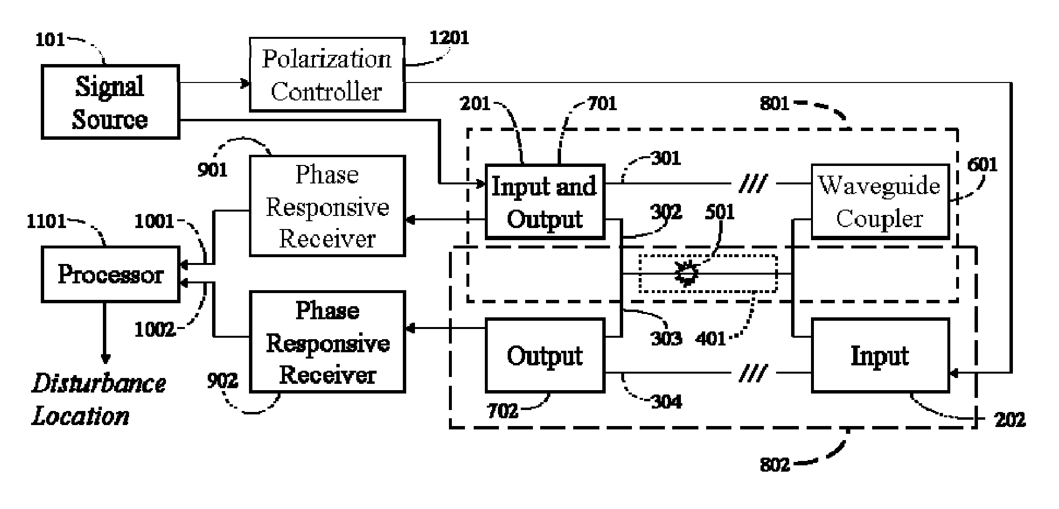
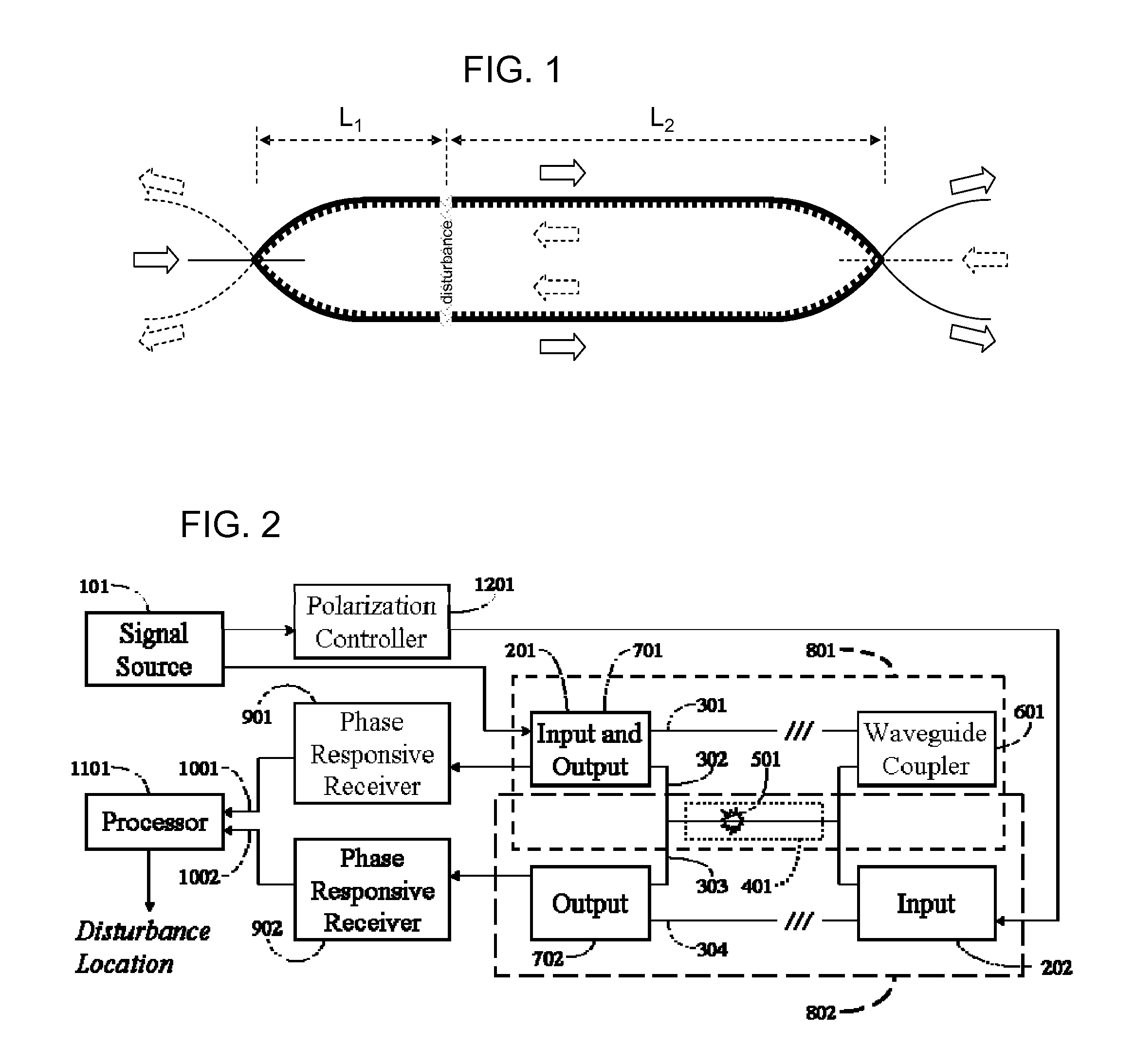
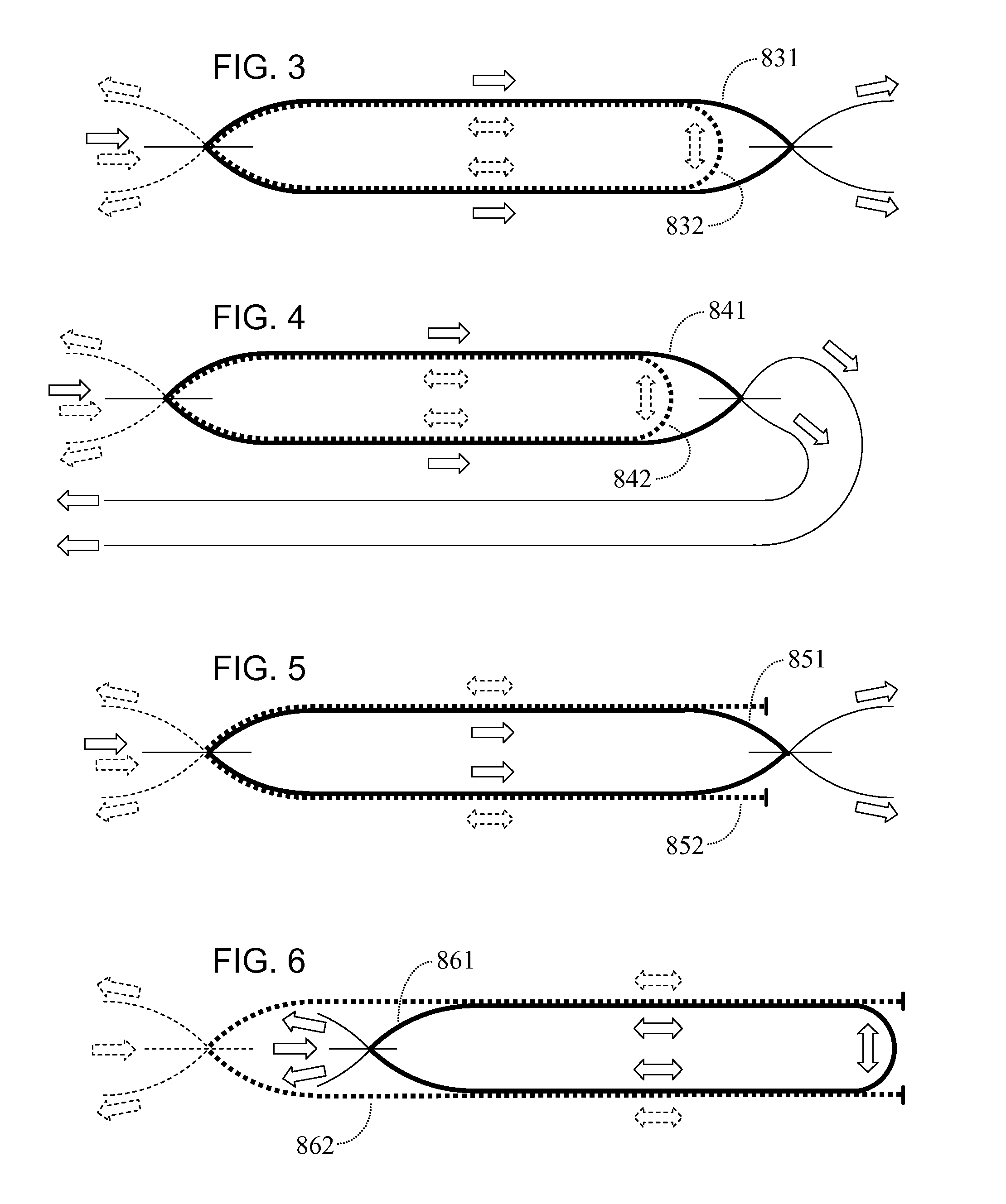
[0037]According to respective embodiments of the invention disclosed herein, a disturbance such as vibration is detected and located along a fiber optic waveguide. Multiple optical fibers or optical fibers carrying multiple signals are configured as two or more interferometers. The interferometers can be of the same or different interferometer types, according to respective embodiments. Signals split from a source are recombined after the signals propagate through the point of the disturbance, where phase variations are induced. Phase responsive receivers at the combiners each produce mutually independent detector signals representing phase relationships between the combined signals. Variations over time in the phase relationships are processed to produce composite signals. The equations embodied by processing differ based on the specific interferometer configuration used. For each interferometer configuration, one embodiment produces composite signals with substantially identical w...


PUM


Abstract

A disturbance, such as vibration from human activity, is located along a fiberoptic waveguide configuration (301-304) with two interferometers (801, 802) of the same or different types, such as Mach-Zehnder, Sagnac, and Michelson interferometers. Carrier signals from a source (101) are split at the interferometer inputs (201, 202) and re-combined at the outputs (701, 702) after propagating through the detection zone (401), where phase variations are induced by the disturbance (501). Phase responsive receivers (901, 902) detect phase relationships (1001, 1002) between the carrier signals over time. A processor (1101) combines the phase relationships into composite signals according to equations that differ for different interferometer configurations, with a time lag between or a ratio of the composite signals representing the location of the disturbance. The detected and composite values are unbounded, permitting phase displacement to exceed the carrier period and allowing disturbances of variable magnitudes to be located.

Description

CROSS REFERENCE TO RELATED APPLICATIONS[0001]This application is a continuation in part of nonprovisional patent application Ser. No. 11 / 570,481, filed Dec. 12, 2006 and claims the priority of provisional patent applications Ser. No. 60 / 841,511, filed Aug. 31, 2006; Ser. No. 60 / 841,595, filed Aug. 31, 2006; and Ser. No. 60 / 845,084, filed Sep. 13, 2006.BACKGROUND OF THE INVENTION[0002]1. Field of the Invention[0003]The invention relates to sensing the effects of a physical disturbance along a signal path, especially human activity at a fence, buried sensing line or other extended sensing path.[0004]A disturbance produces vibration, impact, acoustic noises, stress and / or pressure variations and the like, locally changing one or more signal paths in a manner that produces a time change in the phase relationships between carrier signals propagating along the signal paths, e.g., one or more optical fibers. These phase effects originate at the point of the disturbance and are carried onwa...

Claims


Application Information

Patent Timeline
IPC IPC(8): G01B9/02
CPCG08B13/186
Inventor PATEL, JAYANTILAL S.ZHUANG, ZHIZHONGZADOROZHNY, YURIANNETTA, FRANCESCO A.
Owner OPTELLIOS
Why Eureka
Try Eureka