Joint compound tool

a compound tool and joint technology, applied in coatings, ink reservoir pens, constructions, etc., can solve the problems of wasting time, requiring more time, and requiring more time, so as to save time, eliminate mess, and reduce waste

Inactive Publication Date: 2010-01-21
CAMPBELL SHAWN O +1
View PDF8 Cites 20 Cited by
  • Summary
  • Abstract
  • Description
  • Claims
  • Application Information

AI Technical Summary

Benefits of technology

[0007]In light of the problems associated with applying joint compound to drywall, it is a principal object of the invention to provide a tool that will: stir joint compound (whether ready-mix type or mix-it-yourself type) to a smooth consistency, deliver the stirred joint compound to a desired location on a wall or ceiling, and spread the joint compound at the desired location with minimal intervention on the part of a user. The tool, by its use, saves time, reduces waste, and virtually eliminates the mess normally associated with the blending joint compounds to a smooth consistency.
[0008]It is another object of the invention to provide a tool of the type described that can apply joint compound to a wall in any orientation, reducing stress on the bodies of users. Use of the tool is so easy that it can be operated with one hand.
[0010]Still another object of the invention is to provide a tool that is easily and quickly disassembled and cleaned after use.
[0011]It is an object of the invention to provide improved features and arrangements thereof in a joint compound tool for the purposes described which is lightweight in construction, inexpensive to manufacture, and dependable in use.

Problems solved by technology

Larger houses, and those where optimum finishes are desired, take more time.
Applying joint compound, then, can be time-consuming and costly.

Method used


Image

  • Joint compound tool
  • Joint compound tool
  • Joint compound tool

Examples


Embodiment Construction

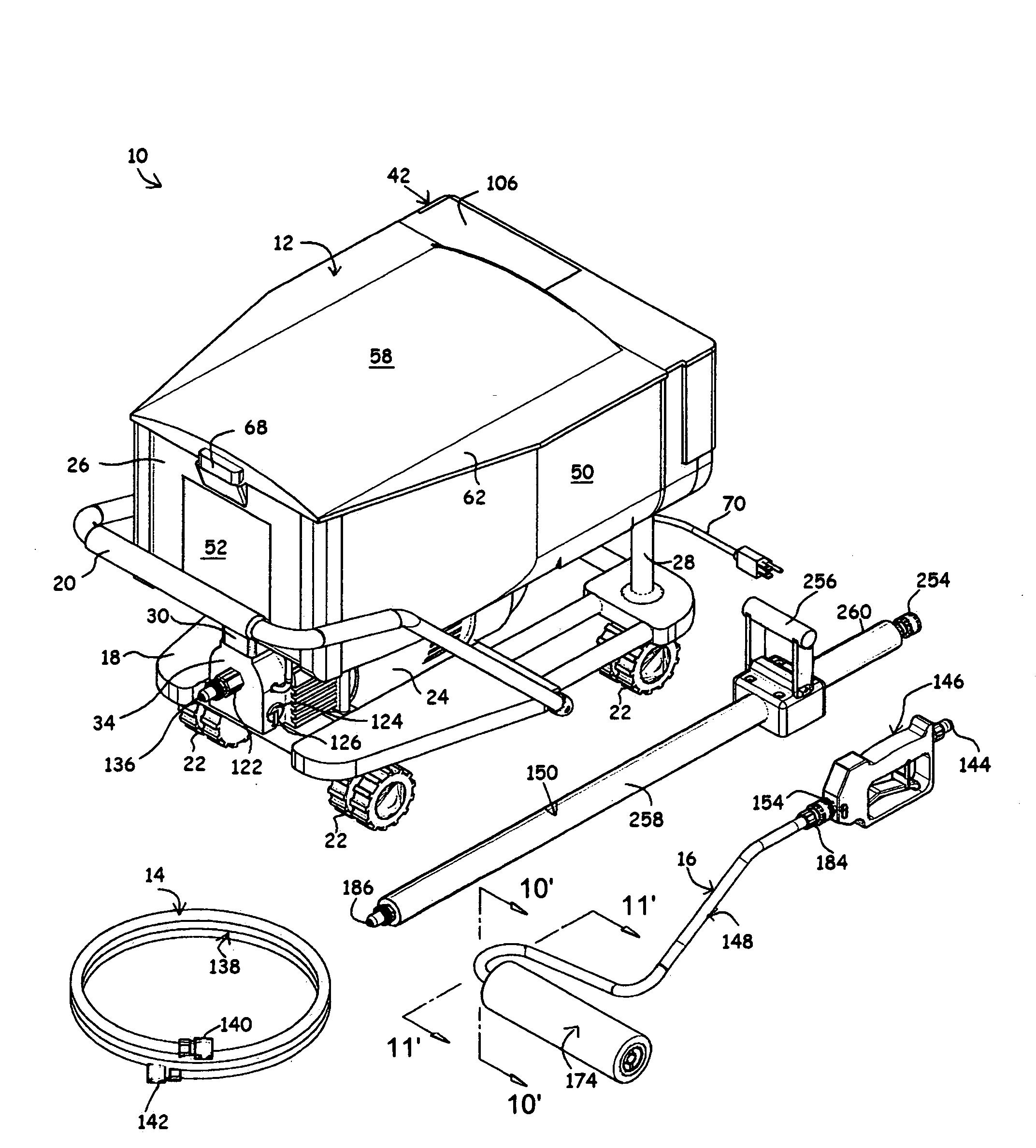
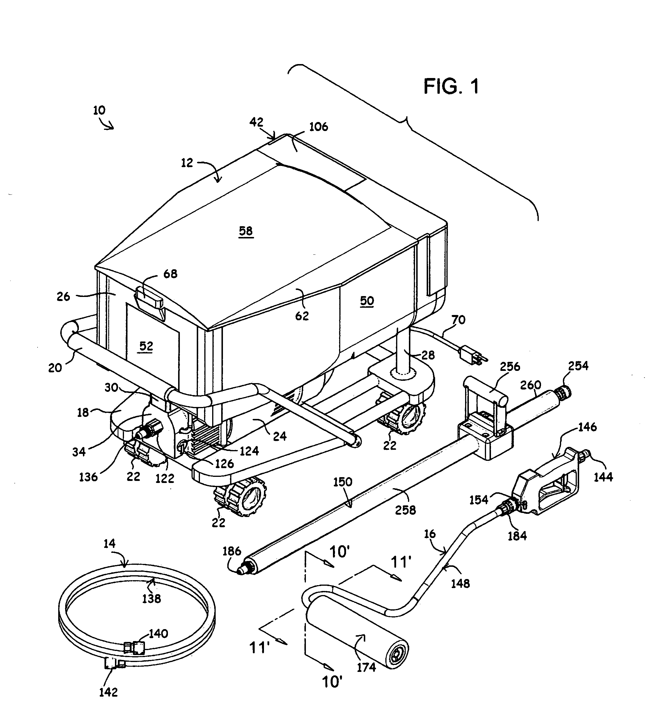
[0027]Referring now to the FIGS., a joint compound tool in accordance with the present invention is shown at 10. Tool 10 includes a mixer 12 for producing joint compound of a smooth consistency. Connected to mixer 12 by means of a flexible hose 14 is an applicator 16 for evenly dispensing joint compound onto drywall.

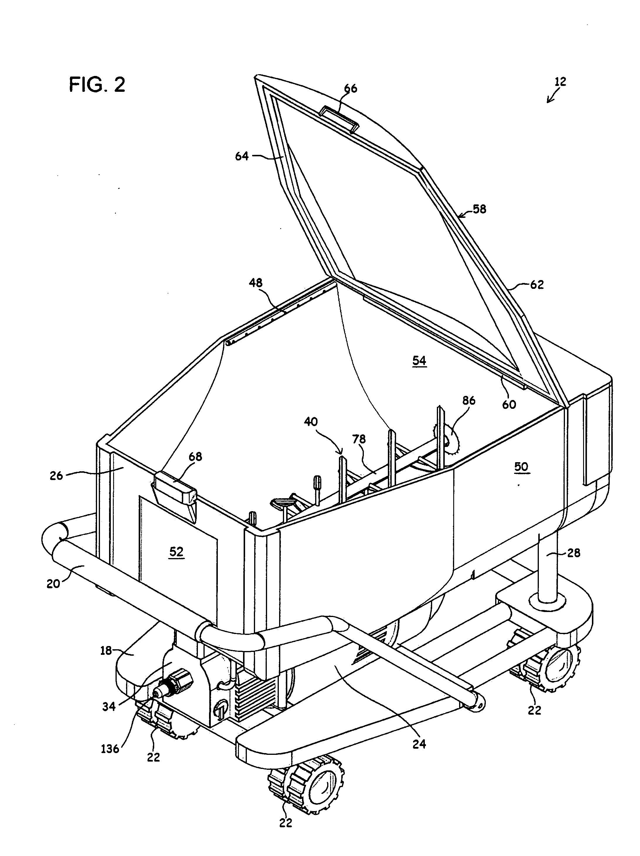
[0028]Mixer 12 includes a rectangular frame 18 having a handlebar 20 extending upwardly therefrom. Frame 18 is supported for movement above the ground by four casters 22, one of which being disposed at each corner of frame 18. Affixed atop frame 18 is a joint compound pump 24 from which hose 14 extends to applicator 16. A hopper 26 is mounted atop pump 24 and is braced by a pair of support posts 28 that extend upwardly from frame 18. A short conduit 30 places the screened outlet 32 at the bottom of hopper 26 in fluid communication with the inlet 34 of pump 24. A heater 36 is affixed to the bottom of hopper 26 adjacent outlet 32. A motor 38 rotates a beater 40 positioned ...


PUM


Abstract

A joint compound tool including a mixer, a hose, and an applicator. The mixer has a hopper and a beater positioned therein. The beater has a rotatable drive shaft that is journaled in the opposed ends of the hopper. A number of first support rods radiate outwardly from the drive shaft remote from the hopper outlet. A pair of intertwined, helical bands encircle the drive shaft and are affixed thereto by the first support rods. A number of second support rods radiate outwardly from the drive shaft adjacent the hopper outlet. A number of blades are secured to the second support rods. A motor is connected to the drive shaft for rotating the beater. A pump is connected to the hopper outlet for pressurizing joint compound received from the hopper. A hose connects the pump to a joint compound applicator having a valve assembly for controlling the flow of joint compound received from the hose and a roller assembly for applying joint compound to drywall.

Description

FIELD OF THE INVENTION[0001]The present invention relates generally to coating implements with material supply and, more particularly, to such implements where material flows through a hollow roller.BACKGROUND OF THE INVENTION[0002]Drywall is a manufactured building material used for constructing walls and ceilings within buildings. In commercial construction, the work of installing and finishing drywall is often split between: “hangers” who secure drywall sheets to wall studs or ceiling joists, “tapers” who conceal the joints between drywall sheets with joint tape, and “mudmen” who conceal the joint tape and any nailheads with several layers of joint compound which is often called “mud.” After applying the joint compound, it is allowed to air dry and then sanded smooth in preparation for painting.[0003]Joint compound is a mixture of water, limestone, perlite, a polymer and clay. This combination of ingredients gives joint compound a creamy texture which allows it to be easily sprea...

Claims


Application Information

Patent Timeline
Patent Type & Authority Applications(United States)
IPC IPC(8): B43K5/02B05C17/00
CPCB05C17/0308E04F21/165E04F21/08B05C17/0333
Inventor CAMPBELL, SHAWN O.YOUNG, HORACE S.
Owner CAMPBELL SHAWN O
Why Eureka
Try Eureka