Knee prostheses with enhanced kinematics

a technology of kinematics and knees, applied in the field of knee prostheses, can solve the problems of deteriorating the bones, articular cartilage and ligaments of the knee, reducing range of motion, and even pre-operative knee soft tissue, which is used to cause flexion and extension in a healthy knee,

Active Publication Date: 2010-01-21
DEPUY (IRELAND) LTD
View PDF0 Cites 150 Cited by
  • Summary
  • Abstract
  • Description
  • Claims
  • Application Information

AI Technical Summary

Benefits of technology

[0023]The above-described features and advantages, as well as others, will become more readily apparent to th

Problems solved by technology

Damage or disease can deteriorate the bones, articular cartilage and ligaments of the knee.
Such changes from the normal condition of the knee joint can ultimately affect the ability of the natural knee to function properly leading to pain and reduced range of motion.
Accordingly, the configuration of soft tissue used to cause movement such as flexion and extension in a healthy knee, or even a pre-operative knee, no longer achieves the same results when the knee is replaced with a prosthesis.
Additionally, the sacrifice of soft tissue results in reduced stability of the knee joint.
The

Method used


Image

  • Knee prostheses with enhanced kinematics
  • Knee prostheses with enhanced kinematics
  • Knee prostheses with enhanced kinematics

Examples


Embodiment Construction

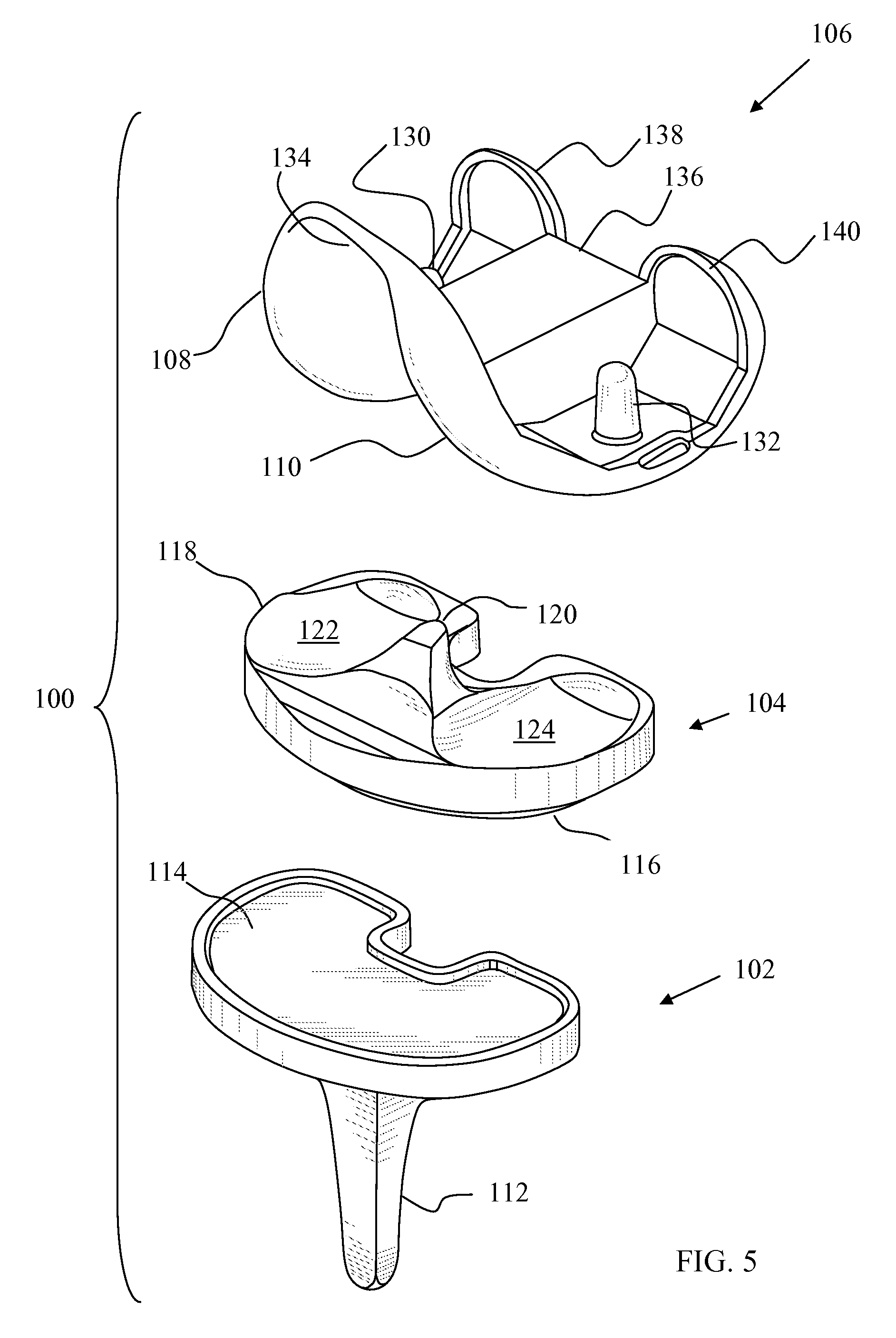
[0056]FIG. 5 depicts a knee replacement system 100. The knee replacement system 100 includes a tibial tray 102, a tibial bearing insert 104 and a femoral component 106 having two femoral condyle elements 108 and 110. The tibial tray 102 includes an inferior stem 112 for attaching the tibial tray 102 to the tibia of a patient and a superior plateau 114 for receiving the tibial bearing insert 104. The tibial bearing insert 104 in this embodiment is fixed and includes an inferior tibial tray contacting surface 116 and a superior tibial bearing surface 118 configured to articulate with the femoral condyle elements 108 and 110. A spine 120 separates the superior tibial bearing surface 118 into a bearing surface 122 and a bearing surface 124.

[0057]The femoral component 106 includes two pegs 130 and 132 which are used to attach the femoral component 106 to the femur of a patient. A trochlear groove 134 is formed between the femoral condyle elements 108 and 110. The trochlear groove 134 pro...


PUM


Abstract

A knee replacement system includes a proximal tibial posterior camming portion defined by a first radius of curvature with a first origin in a first medio-lateral plane, a distal tibial posterior camming portion defined by a second radius of curvature with a second origin in a second medio-lateral plane, an anterior femoral camming portion of a posterior cam defined by a third radius of curvature with a third origin in the first medio-lateral plane, and a posterior femoral camming portion of the posterior cam and defined by a fourth radius of curvature with a fourth origin in the second medio-lateral plane, wherein the second origin is closer to the lateral tibial portion than the first origin, or the fourth origin is closer to the medial femoral portion than the third origin.

Description

[0001]Cross-reference is made to U.S. Utility patent application Ser. No. 12 / 165,579 entitled “Orthopaedic Femoral Component Having Controlled Condylar Curvature” by John L. Williams et al., which was filed on Jun. 30, 2008; to U.S. Utility patent application Ser. No. 12 / 165,574 entitled “Posterior Cruciate-Retaining Orthopaedic Knee Prosthesis Having Controlled Condylar Curvature” by Christel M. Wagner, which was filed on Jun. 30, 2008; to U.S. Utility patent application Ser. No. 12 / 165,575 entitled “Posterior Stabilized Orthopaedic Knee Prosthesis Having Controlled Condylar Curvature” by Joseph G. Wyss, which was filed on Jun. 30, 2008; to U.S. Utility patent application Ser. No. 12 / 165,582 entitled “Posterior Stabilized Orthopaedic Prosthesis” by Joseph G. Wyss, which was filed on Jun. 30, 2008; to U.S. Utility patent application Ser. No. 12 / 174,507 entitled “Antero-Posterior Placement of Axis of Rotation for a Rotating Platform” by John L. Williams, et al., which was filed on Ju...

Claims


Application Information

Patent Timeline
IPC IPC(8): A61F2/38
CPCA61F2/3886
Inventor WYSS, JOSEPH G.WILLIAMS, JOHN L.GOMAA, SAID T.
Owner DEPUY (IRELAND) LTD
Why Eureka
Try Eureka